

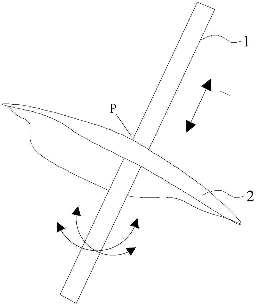
Robotic arm and how it works
A technology of a mechanical arm and a linkage mechanism, applied in the field of medical equipment, can solve the problems of large occupied space, low transmission accuracy and efficiency, complex structure, etc., and achieve the effects of reducing weight, reducing structural difficulty, and improving transmission efficiency.
- Summary
- Abstract
- Description
- Claims
- Application Information
AI Technical Summary
Problems solved by technology
Method used
Image

Examples
Embodiment 1
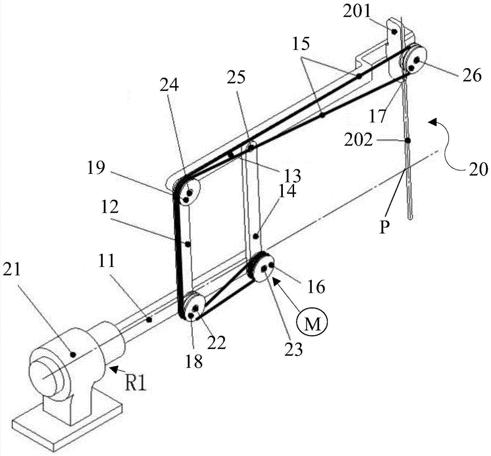
[0045] figure 2 It is an isometric view of the mechanical arm of Embodiment 1 of the present invention. image 3 for figure 2 Front view of the robotic arm shown.
[0046] Such as Figure 2~3 As shown, the mechanical arm is suitable for a robot, especially for a minimally invasive surgical robot, including a linkage mechanism, a flexible transmission mechanism, a connector and a first drive device; the linkage mechanism includes a fixed rod of the first body 11. The first driving rod 12, the connecting rod 13 comprising the second body and the first distal end extension and the second driving rod 14, the fixed rod 11, the first driving rod 12, the connecting rod 13 and the second driving rod 14 Turn and connect in turn to form four connection points P1, P2, P3, P4 (in the embodiment of this application, the first connection point P1, the second connection point P2, the third connection point P3 and the fourth connection point P4 are directly abbreviated For connecting po...
Embodiment 2
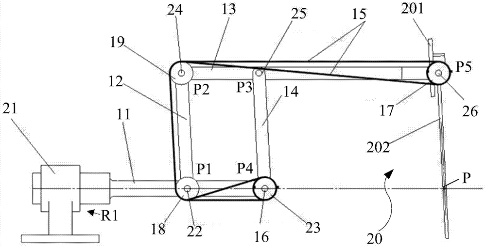
[0066] The difference between the second embodiment and the first embodiment is: the flexible transmission mechanism of this embodiment also includes at least one steering wheel 27, and under the drive of the first driving device, the first driving rod 12 and the main driving wheel 16 of this embodiment Synchronous rotation, correspondingly, the installation positions of the main drive wheel 16, the two transmission wheels and the way around the flexible structure 15 have also been adjusted, see for details Figure 4 and Figure 5 . Here, the same parts of the second embodiment and the first embodiment will not be described in detail in this embodiment, and refer to the first embodiment accordingly. Figure 4 It is an isometric view of the mechanical arm of the second embodiment of the present invention. Figure 5 for Figure 4 Front view of the robotic arm shown.
[0067] Such as Figure 4~5 As shown, the main drive wheel 16 is located at the connection point P1, and the...
PUM
 Abstract
Description
Claims
Application Information