
Compensation method and apparatus for a coriolis flow meter

A flow meter and flow technology, applied in the direction of direct mass flow meter, mass flow measurement device, liquid/fluid solid measurement, etc., can solve the time difference of temperature change, inaccurate and inaccurate output signal of temperature compensation flow rate, etc.

Active Publication Date: 2007-08-29
EMERSON ELECTRIC CO
View PDF3 Cites 4 Cited by
  • Summary
  • Abstract
  • Description
  • Claims
  • Application Information

AI Technical Summary

Problems solved by technology

This results in an inaccurate output signal for the temperature compensated flow rate produced by the electronics
[0008] A second disadvantage of using thermal sensors is that because they are not mounted on the moving part of the oscillating flow tube, there is a time lag between the time the thermal sensor detects a thermal change and the time the flow tube material changes temperature
This time difference further causes inaccuracies in the compensated mass flow rate output signal produced by the flowmeter

Method used


Image

  • Compensation method and apparatus for a coriolis flow meter
  • Compensation method and apparatus for a coriolis flow meter
  • Compensation method and apparatus for a coriolis flow meter

Examples


Embodiment Construction

[0130] the term

[0131] FCF Current Technology Flow Calibration Factor

[0132] α current technology FCF temperature coefficient

[0133] The Δt flow causes a time delay

[0134] Δt 0 Nominal time delay for zero flow

[0135] mass flow rate

[0136] F Operating drive frequency

[0137] f 0 Manufacturer's choice of rated drive frequency (under typical thermal conditions)

[0138] ZERO(F) describes the effect frequency without nominal time delay, Δt 0 equal to Δt 0+ (F-F 0 )α F

[0139] alpha F Linear frequency constant for zero

[0140] Proportionality factor relating Δt to mass flow. Similar to FCF in current technology.

[0141] The linear frequency (temporary) coefficients of . Similar to alpha in current technology.

[0142] FMUT Flowmeter under test.

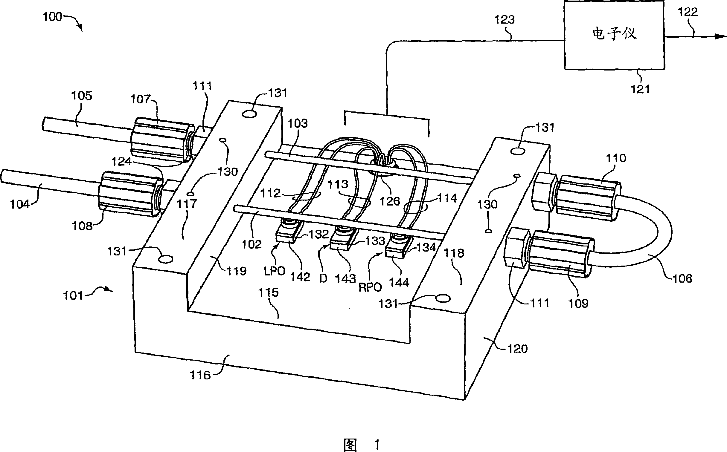
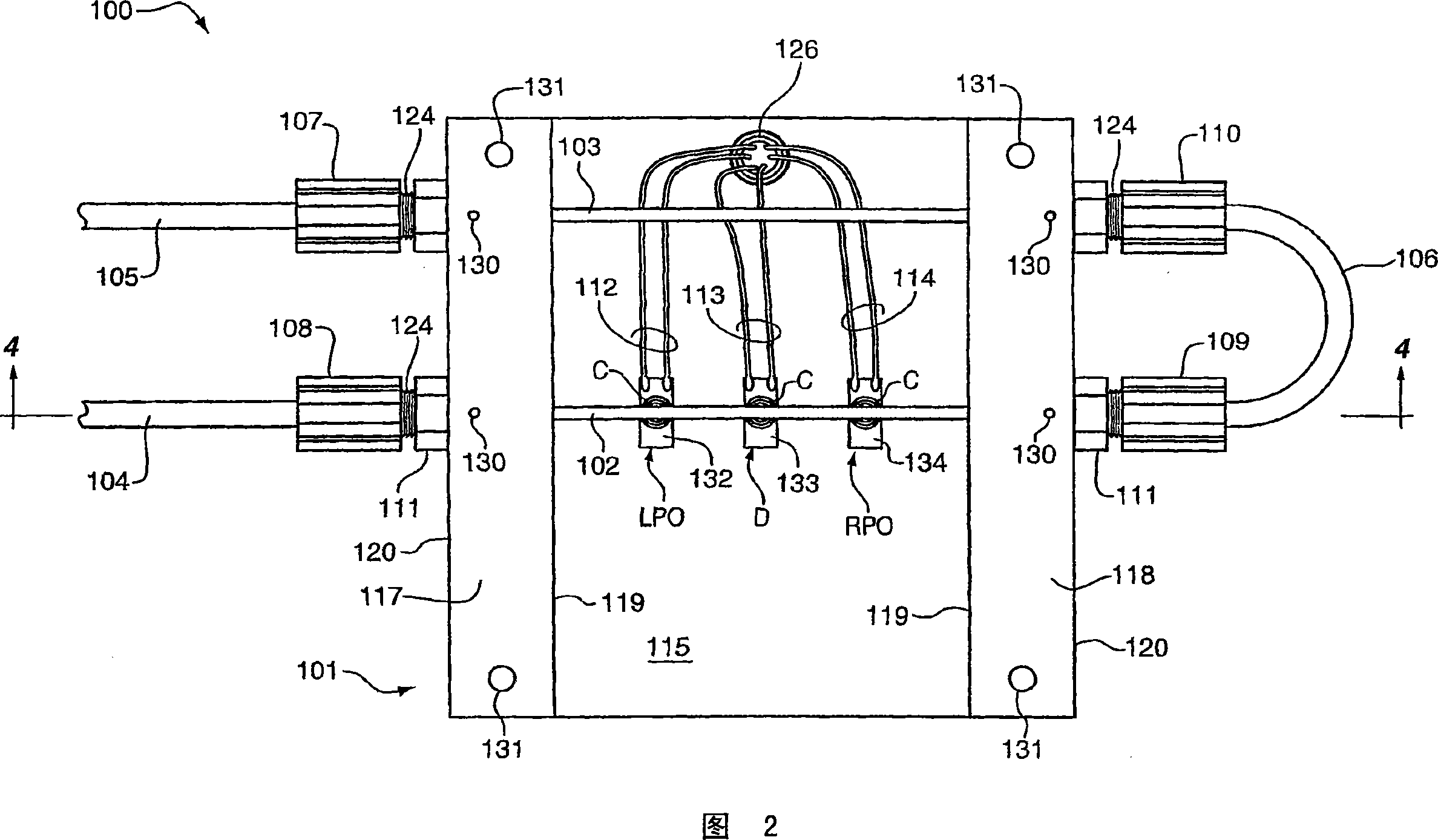
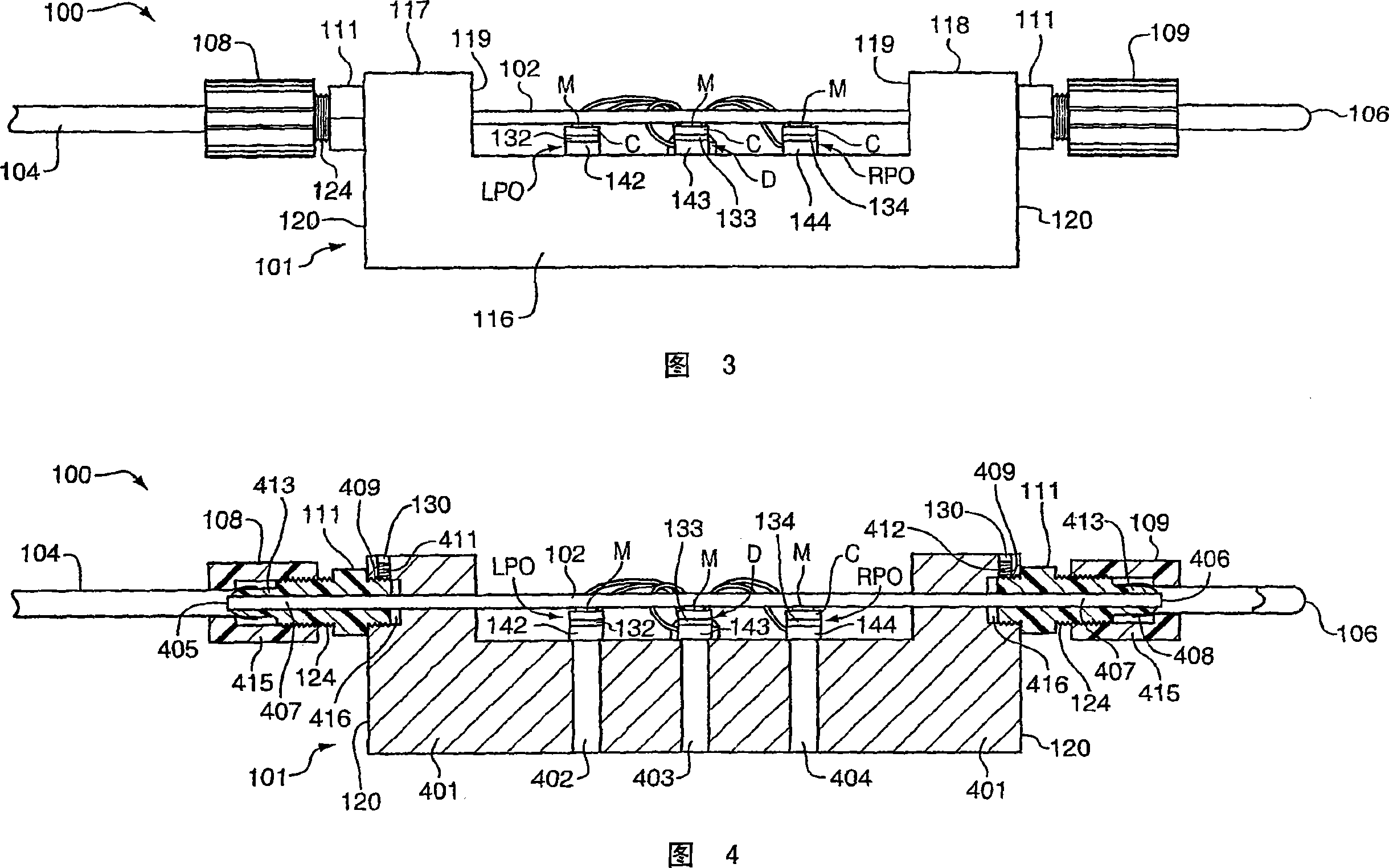
[0143] Description of Figure 1

[0144] Figure 1 is a perspective view of a first possible exemplary embodiment of a Coriolis flowmeter embodying the present invention. The figure shows a ...


PUM


Abstract

The present invention discloses a method and apparatus (121) for providing temperature flow rate compensation for a Coriolis flow meter. The described compensation compensates for the flow oscillation factor and the nominal time delay referred to as "zero" in the current technology. After a Coriolis flow meter is installed in a process, whether the flow meter is used for calibration or for actual process use, it only needs to be zeroed once throughout its lifetime after installation. This is a significant improvement over current technology Coriolis flow meters which may need to be re-zeroed after minor changes in pressure or temperature or after installation.

Description

technical field [0001] The present invention relates to compensation methods and apparatus for Corioli flowmeters. Background technique [0002] The use of Coriolis effect mass flow meters to measure the mass flow rate and other information of materials flowing through pipelines is known, as in U.S. Patent No. 4,491,025 issued to J.E. Smith et al. on January 1, 1985 and on February 11, 1882 Disclosed in Re. 31,450, dated J.E. Smith. Each material filled in a flow tube is driven to oscillate at the resonance of one of these natural modes. This natural mode of oscillation is defined in part by the combined mass of the flow tube and the material in the flow tube. Material flows into the flowmeter from a line connected on the inlet side. The material then passes through one or more flow tubes and is conveyed to a pipeline connected on the outlet side. [0003] The driver applies a force that causes the flow tube to oscillate. When there is no flow through the Coriolis flowm...

Claims


Application Information

Patent Timeline
Patent Type & Authority Applications(China)
IPC IPC(8): G01F1/84G01F25/00
CPCG01F25/00G01F15/024G01F1/8409G01F1/8436G01F1/849G01F1/8413G01F1/84
Inventor M·A·施洛泽J·C·迪尔J·L·怀特利
Owner EMERSON ELECTRIC CO
Learn More