Steel fibre with multi-anchor fixed point

A technology of steel fibers and anchor points, applied in the field of steel fibers, can solve the problems of increasing the flexural resistance and cracking performance of concrete, small gripping force and anchoring force, etc.

Inactive Publication Date: 2007-09-05
武汉新途工程新材料科技有限公司
View PDF0 Cites 5 Cited by
  • Summary
  • Abstract
  • Description
  • Claims
  • Application Information

AI Technical Summary

Problems solved by technology

The existing steel fiber has two structural forms, one is the end hook shape and the shield bell shape. The two ends of the steel fiber of these two structures have only one anchor segment, that is, only one anchor point is formed. This steel fiber and concrete The holding force and anchoring force are small, and it is limited to increase the flexural and cracking properties of concrete

Method used


Image

  • Steel fibre with multi-anchor fixed point
  • Steel fibre with multi-anchor fixed point

Examples


Embodiment Construction

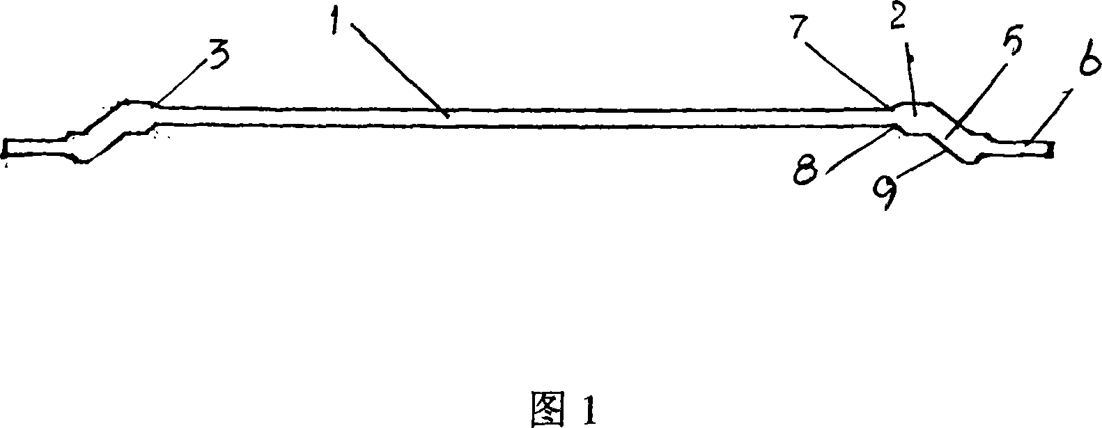
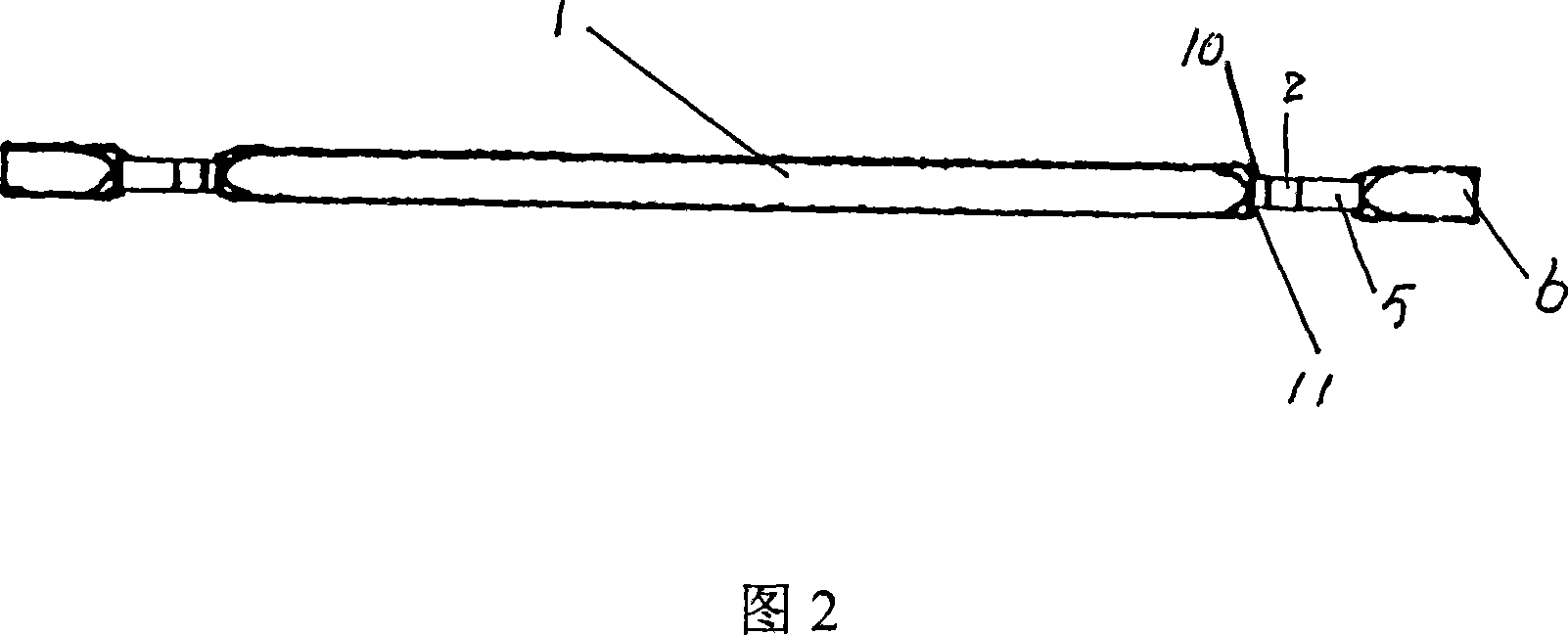
[0009] As shown in Figure 1, the cross-section of the connecting section 1 of the steel fiber is flat and straight, and is formed by cold rolling with a circular section. Section 2, between the first anchoring section 2 and the middle connecting section 1 is a vertical plane connection or an inclined plane connection, and this embodiment adopts an inclined plane connection 3 for transition. The protruding portion of the first anchoring segment 2 is in a vertical plane. The cross section of the first anchoring section 2 is circular. There is a second anchoring section 5 connected to the first anchoring section 2, and there is an obtuse angle between the second anchoring section 5 and the axis of the first anchoring section 2, and the included angle is 120-150°: the second anchoring section 5 The cross section is circular; the third anchoring section 6 is connected to the second anchoring section 5, and there is an included angle between the third anchoring section 6 and the ax...


PUM


Abstract

A steel fiber with multi anchor points includes a middle section with two ends fixed with the first anchor zone extruded out of the first plane, a second anchor zone connected to the first one in an obtuse angle, a third anchor zone connected to the second one with an angle, which is extruded from the second plane.

Description

technical field [0001] The invention belongs to building accessories, in particular to a steel fiber in concrete. Background technique [0002] Steel fibers have been widely used in concrete to enhance the flexural and cracking properties of concrete. The existing steel fiber has two structural forms, one is the end hook shape and the shield bell shape. The two ends of the steel fiber of these two structures have only one anchor segment, that is, only one anchor point is formed. This steel fiber and concrete The holding force and anchoring force are small, and the increase in the flexural and cracking properties of concrete is limited. There is a ball-mark type steel fiber patent product, which distributes concave-convex ball marks at both ends of the main section of the steel fiber, and forms anchor points at the ball-mark parts, that is, one ball-mark site forms one anchor point, and it is necessary to form multiple If there are three anchor points, multiple ball marks m...

Claims


Application Information

Patent Timeline
Patent Type & Authority Applications(China)
IPC IPC(8): E04C5/03
Inventor 马堂英
Owner 武汉新途工程新材料科技有限公司
Why Eureka
Try Eureka