Method for controlling traffic signal light with inverse-hour display

A technology of a traffic signal light and a control method, which is applied to the countdown display control field of a traffic signal light, can solve problems such as increasing time, and achieve the effects of simple mechanism and cost reduction.

Active Publication Date: 2007-09-05
WUXI ANBANG ELECTRIC CO LTD
View PDF0 Cites 18 Cited by
  • Summary
  • Abstract
  • Description
  • Claims
  • Application Information

AI Technical Summary

Problems solved by technology

If it is multiple detections, it is not app

Method used


Image

  • Method for controlling traffic signal light with inverse-hour display
  • Method for controlling traffic signal light with inverse-hour display
  • Method for controlling traffic signal light with inverse-hour display

Examples


Embodiment Construction

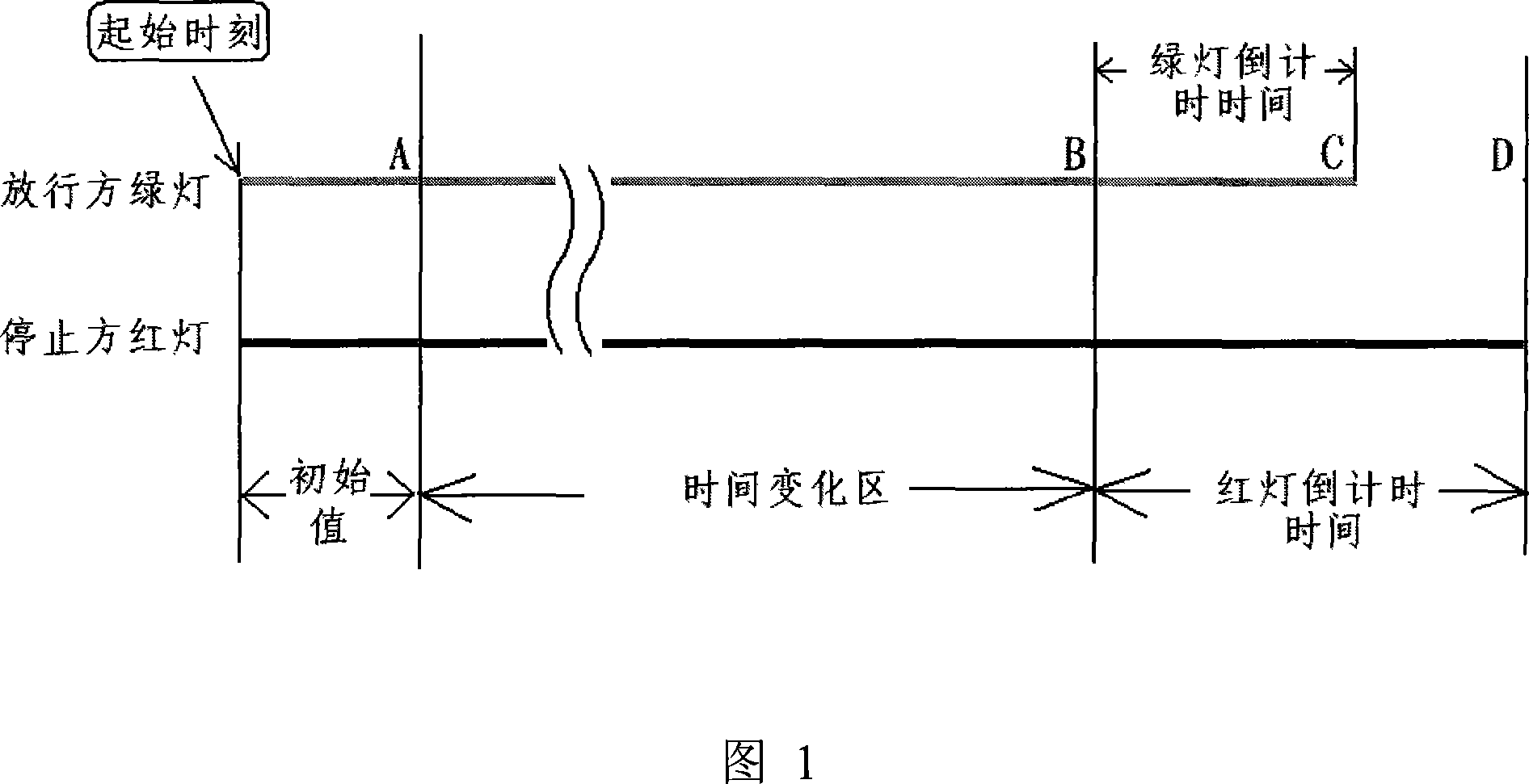
[0029]As shown in FIG. 1 , it is a schematic diagram for explaining timing time points of the traffic signal light countdown display control method of the present invention. Taking the green light as an example, the traffic signal light countdown display control method of the present invention first utilizes a vehicle detector (now generally uses an induction coil buried under the road) to detect vehicle flow; The machine sets the initial value A of the green light passing time according to the traffic flow data or the green light passing time initial value A according to the detected vehicle conditions, and detects (single or multiple) traffic flow during execution to adjust the release time, that is, in During the time period A-B, detect the traffic flow for several times, and adjust the green light release time at the same time. Set a period of time as the countdown time, generally 20 seconds; the third step is to obtain the countdown start time signal determined in step (2...


PUM


Abstract

A method for controlling back-word timing display of traffic signal lamp includes using vehicle detector to detect vehicle flow rate, transmitting obtained vehicle flow rate signal to annunciator, setting time initial value of passing or no-passing by annunciator according to vehicle flow rate data and regulating said passing or no-passing time timely by detecting vehicle flow rate in execution process.

Description

technical field [0001] The invention relates to a countdown display control method of a traffic signal light, in particular to a method for displaying a period of countdown time corresponding to the remaining red light or the remaining green light of an intersection phase by using a yellow light (composite traffic signal light). Background technique [0002] First, an explanation of the relevant terms. 1. Phase: A group of signal lights that can independently indicate passage in one direction; 2. Red light countdown time: a preset red light time for any phase to run before giving the right of way; 3. Green light countdown time: any phase A period of preset green light time before the end of the right of way; the purpose of the countdown display device is to cooperate with the phase transition of the traffic signal light to remind the driver of the vehicle to be ready to pass or stop, so as to pass the intersection quickly and safely, so as to ensure road traffic Safe and sm...

Claims


Application Information

Patent Timeline
IPC IPC(8): G08G1/08G08G1/096
Inventor 王耀明谢一明
Owner WUXI ANBANG ELECTRIC CO LTD
Why Eureka
Try Eureka