Driving circuit and reset circuit for plasma display panel

A display panel and reset circuit technology, which is applied in the direction of identification devices, static indicators, instruments, etc., can solve the problem that the resonance of the maintenance circuit 101 is different from the resonance of the reset waveform, the maintenance period of the display unit is shortened, and the capacitor Cp is overvoltage Slow down and other issues to achieve the effect of shortening the reset period, improving display quality, and shortening the reset period

Inactive Publication Date: 2007-09-05
CHUNGHWA PICTURE TUBES LTD
View PDF0 Cites 0 Cited by
  • Summary
  • Abstract
  • Description
  • Claims
  • Application Information

AI Technical Summary

Problems solved by technology

[0005] The disadvantage of the above technology is that in order to effectively erase and reset the wall charges, it is necessary to cause a weak discharge, that is, to slowly reduce the voltage across the capacitor Cp, which requires a long reset period.
However, the longer the reset period, the longer the backlight will be on, and the maintenance period that determines the average brightness of the display unit will be relatively shortened. These factors will reduce the display quality
In addition, the resistor R requires a more complicated process and higher cost
[0006] Although the sustaining circuit 101 can provide the resonance of the inductor Ls and the capacitor Cp, its resonant frequency is greatly different from the frequency required for the reset waveform, and the resonance of the sustaining circuit 101 and the resonant effect of the reset waveform are also different. limitations and limitations

Method used


Image

  • Driving circuit and reset circuit for plasma display panel
  • Driving circuit and reset circuit for plasma display panel

Examples


Embodiment Construction

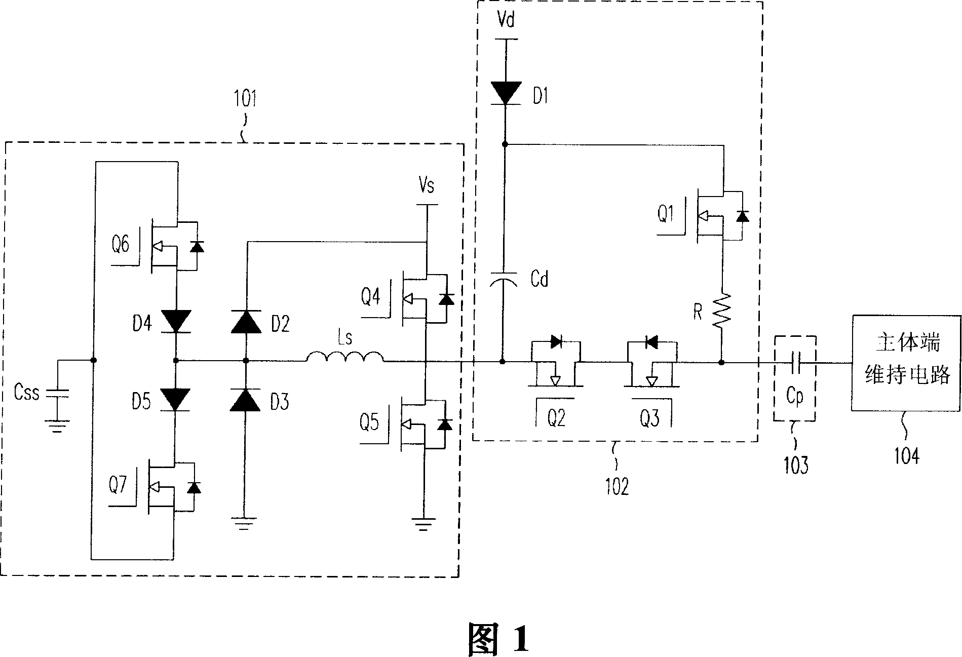
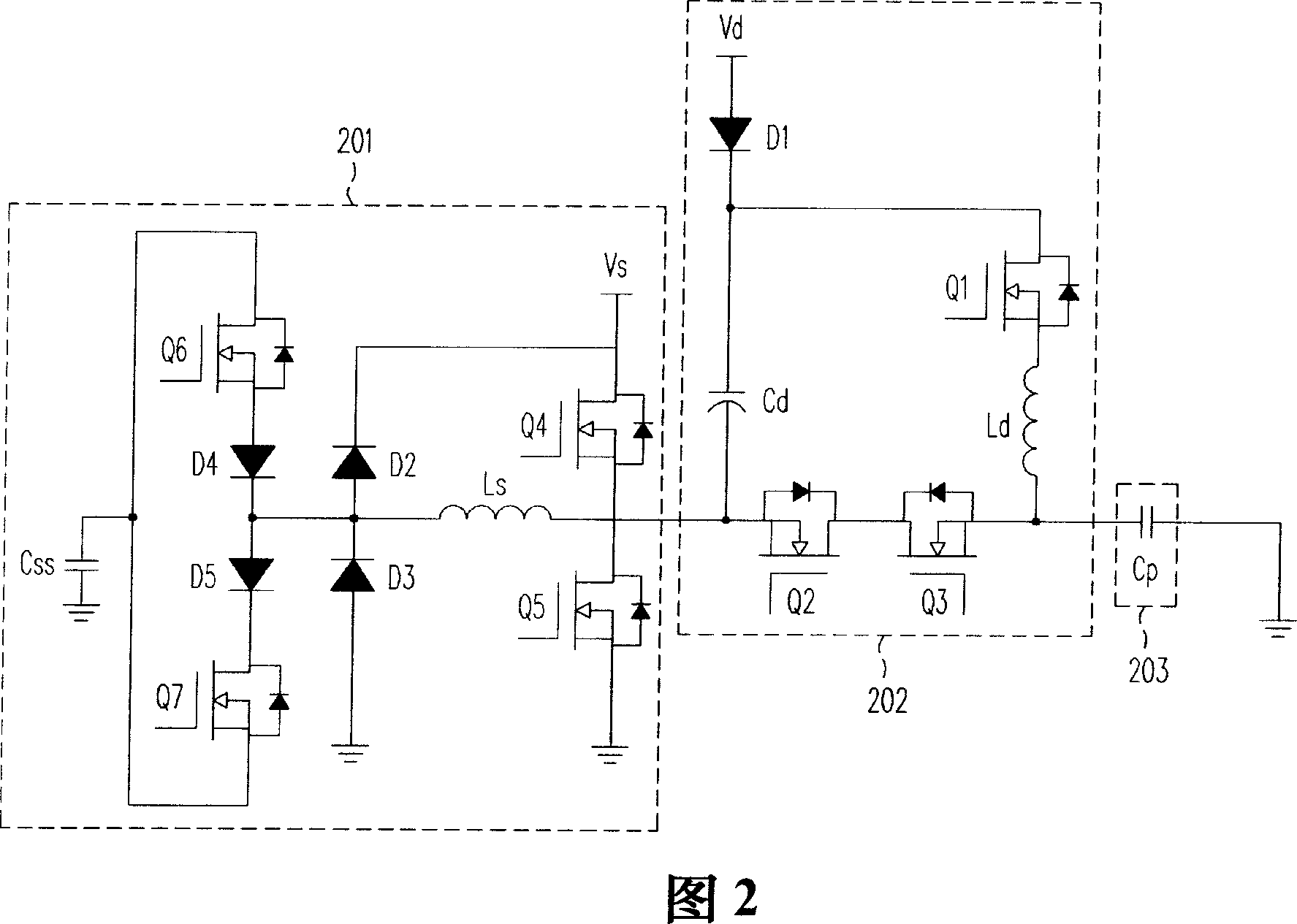
[0031] FIG. 2 is a schematic diagram of a PDP driving circuit according to an embodiment of the invention. The driving circuit in FIG. 2 includes a reset circuit 202 and a sustain circuit 201 . The reset circuit 202 is electrically connected to one of the display units 203 of the PDP, and generates a reset waveform of the display unit 203 by LC resonance. The sustain circuit 201 provides a sustain voltage to the display unit 203 during the sustain period.

[0032] The main difference between the reset circuit 202 of Fig. 2 and the reset circuit 102 of Fig. 1 is that the resistor R of Fig. 1 is changed into the inductor Ld of Fig. 2, and its purpose is to change the traditional resistance-capacitor resonance into the inductance of the present invention Capacitive resonance. On the other hand, the architecture of the sustain circuit 201 in FIG. 2 is the same as that of the sustain circuit 101 in FIG. 1 . The reset circuit 202 of this embodiment is electrically connected to th...


PUM


Abstract

A driving circuit of plasma display face plate is prepared as connecting reset circuit with display unit of plasma display face plate to use inductance capacity resonant to generate reset waveform of said display unit and using maintenance circuit to provide maintenance voltage to said display unit at maintaining period.

Description

technical field [0001] The present invention relates to a driving circuit of a plasma display panel (PDP for short), and in particular to a reset circuit of a plasma display panel. Background technique [0002] During the driving process of the plasma display panel, a reset period, an addressing period and a sustain period are repeated in sequence. Wherein, the purpose of the reset period is to erase and reset the wall charge of the PDP display unit (cell). The purpose of the scan period is to address the display cells. The purpose of the sustain period is to maintain the brightness of the addressed display unit. [0003] FIG. 1 is a schematic diagram of a conventional PDP driving circuit. To simplify the description, FIG. 1 only shows one display unit 103 and its related driving circuit, and the circuits required during the scanning period are also omitted and not shown in FIG. 1 . The display unit 103 has three electrodes, namely a scan electrode, a bulk electrode and ...

Claims


Application Information

Patent Timeline
Patent Type & Authority Applications(China)
IPC IPC(8): G09G3/28G09G3/20H01J17/49G09F9/313G09G3/296
Inventor 林琦修林明璋
Owner CHUNGHWA PICTURE TUBES LTD
Why Eureka
Try Eureka