Sealing bush, hydraulic unit, and check valve

A sealing bushing and sealing device technology, applied in the direction of the valve device, the parts in contact with the valve element and the valve seat, and the lifting valve, etc., can solve the problem of expensive manufacturing of the sealing bushing, achieve simple and accurate manufacturing, and reduce assembly The effect of work

Active Publication Date: 2010-12-15
BOSCH REXROTH AG
View PDF8 Cites 2 Cited by
  • Summary
  • Abstract
  • Description
  • Claims
  • Application Information

AI Technical Summary

Problems solved by technology

[0003] Since this sealing bush must be machined from metal, and the sealing ring is installed on the outer circumference as a separate component, this kind of sealing bush is relatively expensive to manufacture

Method used


Image

  • Sealing bush, hydraulic unit, and check valve
  • Sealing bush, hydraulic unit, and check valve
  • Sealing bush, hydraulic unit, and check valve

Examples


Embodiment Construction

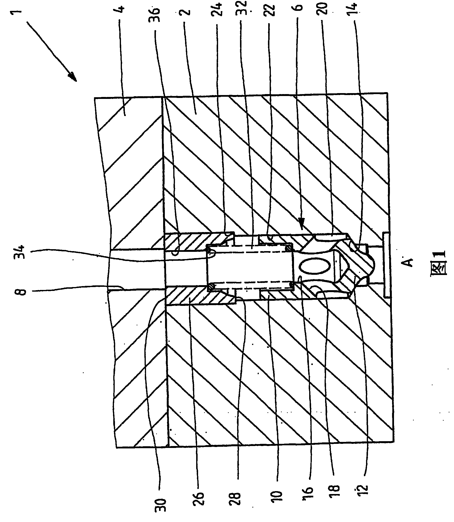
[0025] figure 1 A cross-sectional view of a hydraulic device is shown, eg a motion control block 1 designed as a large plate structure and comprising a disk 2 to which an opposing disk 4 is assigned. A one-way valve 6 is inserted in the disc 2, which, in the locked position shown, blocks the hydraulic fluid flow passage between the inlet A and the outlet passage 8 formed in the opposite disc 4, while the one-way valve 6 is in the locked position shown. The open position controls the connection to open the connection.

[0026] The one-way valve 6 includes a locking element 10 which is biased by a cone 12 against a suitably formed valve seat 14 . The locking element 10 is a hollow piston in which the inner bore 16 opens through an inclined channel 18 in an annular chamber 20 formed by a plurality of dimples on the outer circumference of the locking element 10, each of the inclined holes 18 respectively opening to a dimple. The basic structure of such a locking element 10 is d...


PUM


Abstract

The invention disclosed bushing gasket (26), back valve and hydraulic device which is provided with the bushing gasket. the bushing gasket (26) is made up from plastics, and on the end-face (30) is provided with optimization taper shaped blow-up part (38) which can connect with the supporting shoulder hermetically.

Description

technical field [0001] The invention relates to a sealing bush according to the preamble of claim 1, to a hydraulic device fitted with such a sealing bush, and to a non-return valve. Background technique [0002] In the data sheets of the applicant's RD 20 395 / 12.95 and RD 21 523 / 10.95, one-way valves are disclosed in which a metal locking element is biased against the valve seat by a spring. The spring is supported at its rear on a sealing bush which is inserted into the disc housing the one-way valve or the hydraulic fluid flow passage of the housing. In the known solutions, the sealing bushings are all made of metal and have a sealing ring by which leakage along the outer circumference of the sealing bushing can be prevented. [0003] Such a sealing bushing is relatively expensive to manufacture since it must be machined from metal and the sealing ring is mounted as a separate component on the outer circumference. SUMMARY OF THE INVENTION [0004] The main purpose of ...

Claims


Application Information

Patent Timeline
Patent Type & Authority Patents(China)
IPC IPC(8): F16K15/02F16K25/00F16K1/46
CPCF16K15/026Y10T137/86485Y10T137/7925Y10T137/7869
Inventor 布赖恩·卡纳伯恩德·施米特
Owner BOSCH REXROTH AG
Why Eureka
Try Eureka