

Direct-fluid-supply writing implement
A writing tool and direct-liquid technology, which is applied to writing utensils, printing, and ink pens with ink storage tubes in the pen barrel, etc., which can solve the problems of complex structure, large number of parts, and difficulty in low prices.
- Summary
- Abstract
- Description
- Claims
- Application Information
AI Technical Summary
Problems solved by technology
Method used
Image

Examples
no. 1 Embodiment approach
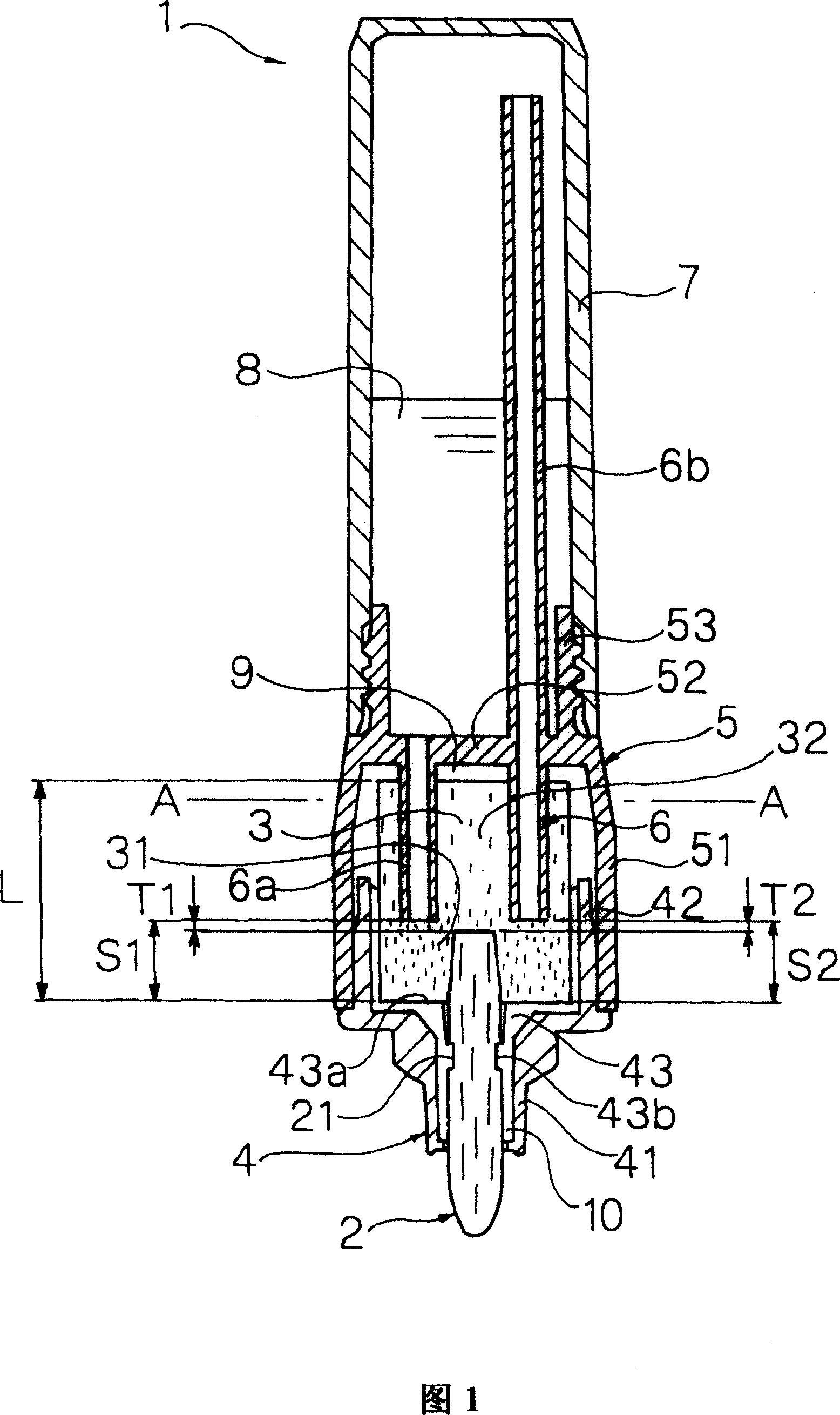
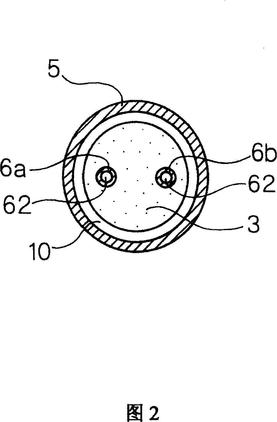
[0190] 1 to 2 show a straight liquid writing instrument 1 according to the first embodiment of the present invention.
[0191] The straight liquid writing instrument of this embodiment is composed of the following parts: a pen tip 2; an ink adsorbing body 3 that is connected to the rear end of the pen tip 2; and an adsorbing body accommodating part that holds the pen tip 2 at the front end and attaches the The ink adsorbent 3 is housed inside; the ink bag 7, which is installed behind the aforementioned ink adsorbent housing portion, and directly stores the ink 8 inside; the partition wall 52, which separates the aforementioned adsorbent housing portion and the aforementioned ink bag 7; And a plurality of (specifically, two) communication tubes 6 which protrude forward from the front surface of the aforementioned partition wall 52 and are pierced and connected to the inside of the ink adsorbent 3. The adsorbent accommodating portion is composed of a tip member 4 that holds the pen ...
no. 2 Embodiment approach
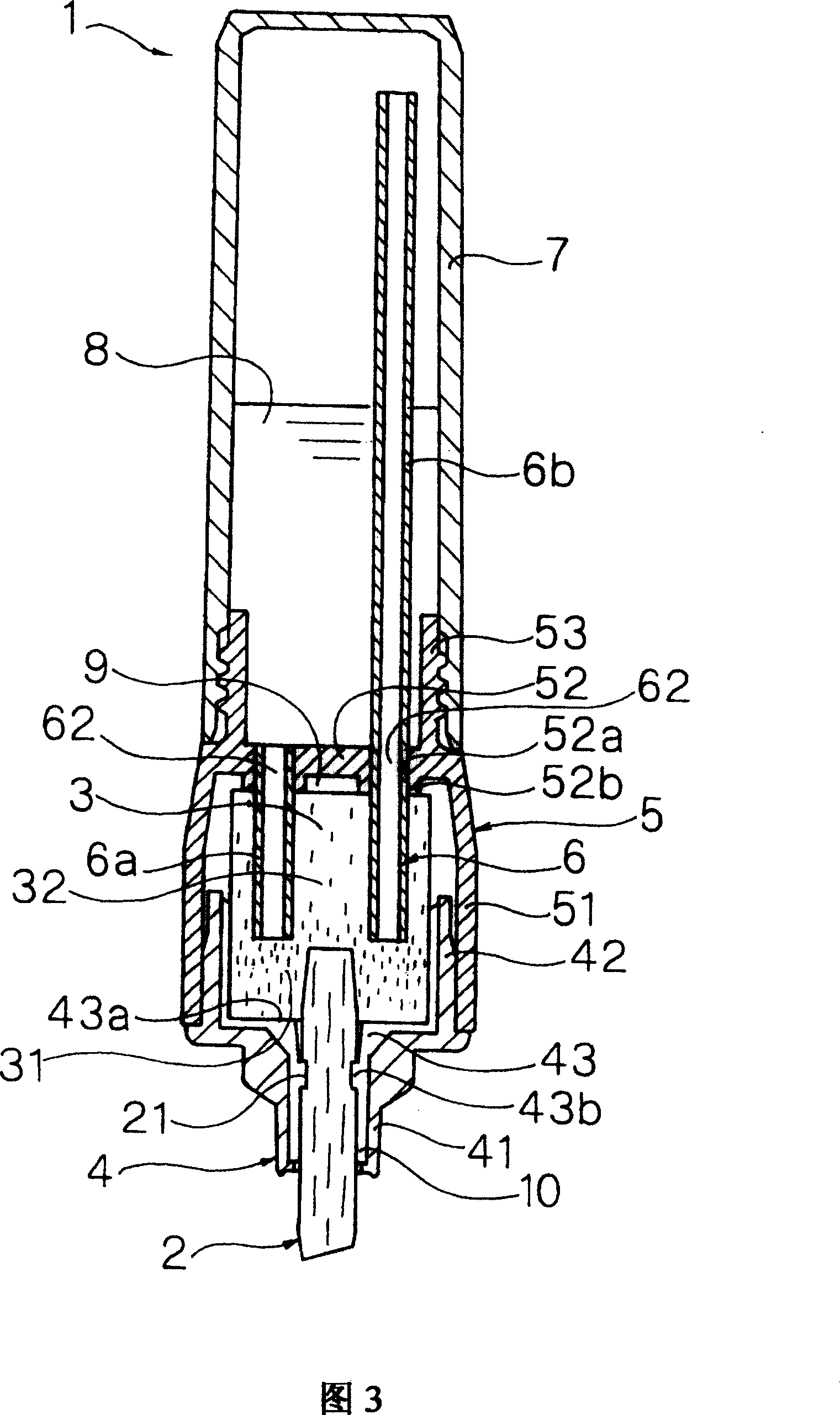
[0215] Fig. 3 shows a second embodiment of the present invention.
[0216] This embodiment is a modified example of the first embodiment, and is different from the first embodiment in that the tip of the pen tip 2 has a chisel shape, and the communication tube 6 and the partition wall 52 are formed of different members.
[0217] The aforementioned partition wall 52 has two mounting holes 52a penetrating in the front-rear direction. The communication pipe 6 is press-fitted and fastened in each of the aforementioned mounting holes 52a. In addition, on the front surface of the partition wall 52, an annular convex portion 52b (abutting wall portion) in which the mounting hole 52a opens forward is integrally formed. The annular convex portion 52b is in contact with the rear end surface of the ink adsorbent 3, and between the rear end surface of the ink adsorbent 3 and the partition wall 52, an appropriate size corresponding to the convex size of the annular convex portion 52b is formed...
no. 3 Embodiment approach
[0219] Fig. 4 shows a third embodiment of the present invention.
[0220] This embodiment is a modification of the first embodiment, and the pen tip 2 is composed of a ballpoint pen core. The aforementioned pen tip 2 is composed of a holder 23 rotatably holding the ball 22 at the front end, and an ink guide member 24 inserted into the holder 23. The aforementioned ink guide member 24 is composed of a rod-shaped resin processed body made of synthetic resin fibers, and its rear end is pierced and inserted from the front end of the ink adsorbent 3 and is located in front of the interior of the ink adsorbent 3. In addition, an air hole 44 is penetrated in the side wall of the small diameter portion 41 of the tip member 4. The air hole 44 communicates the atmosphere with the air passage 10 in the tip member 4.
[0221] The front end of each of the aforementioned communicating pipes 6 is formed by an inclined cut surface 61, which is sharpened. As a result, the piercing and insertion pe...
PUM
 Abstract
Description
Claims
Application Information