
Mountain massif shaft-well chimney highly effective solar energy hot gas flow generating system

A power generation system, solar thermal technology, applied in solar thermal power generation, wind power generation, mechanical power generated by solar energy, etc., can solve the problems of short service life, small temperature difference of heat collection shed, poor thermal insulation performance, etc., and achieve no damage to the ecological environment , fast construction and long service life

Inactive Publication Date: 2010-05-26
沈晓莉
View PDF9 Cites 0 Cited by
  • Summary
  • Abstract
  • Description
  • Claims
  • Application Information

AI Technical Summary

Problems solved by technology

[0002] At present, the invention patent application number: 98104903.6 "Hillside Solar Greenhouse Wind Generation System" and other invention patents, and Spain built the world's first solar thermal power station in 1982, its common disadvantages: 1. Solar heat collection sheds are all used The plastic film is used as the heat collecting material, so the temperature difference between the inside and outside of the heat collecting shed is small (about 20°C), that is, the heat collecting temperature is low
Poor thermal insulation performance, low heat collection efficiency, and short service life; 2. The heat storage adopts stone paving on the ground and thermal insulation layer. This heat storage method has low efficiency and is difficult to adjust and control; 3. The slope chimney only acts as an air duct. Therefore, the chimney utilization rate and power generation efficiency are low
In short, the existing solar thermal power generation systems in the world currently have the problem of low power generation efficiency.

Method used


Image

  • Mountain massif shaft-well chimney highly effective solar energy hot gas flow generating system
  • Mountain massif shaft-well chimney highly effective solar energy hot gas flow generating system
  • Mountain massif shaft-well chimney highly effective solar energy hot gas flow generating system

Examples


Embodiment Construction

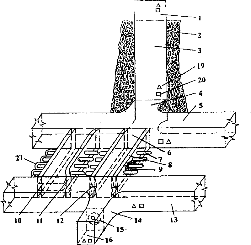
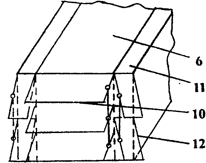
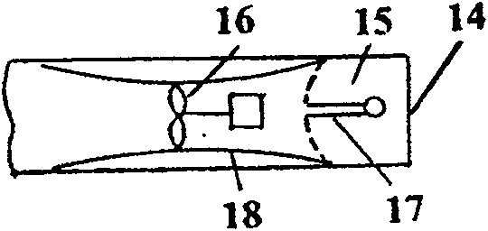
[0016] Accompanying drawing is a kind of specific embodiment of the present invention. This embodiment includes the hot air duct system of the heat collection and storage unit, the hot air collection system of the heat collection and storage unit on the slope of the mountain, and the power generation system.

[0017] The hot air duct system of the present invention comprises a mountain body 2, a mountain top chimney 1 located at the top of the mountain body 2, a mountain chimney 3 located in the mountain body 2, and a mountain flat hole 4, which are successively connected to the upper hot air flow connecting air duct 5 and the mountain slope The hot air duct 6 of the heat collecting and storage unit, the lower end cold air connecting air duct 13 and the cold air inlet air duct 14 . As a result, a solar hot air power generation system that does not consume any energy is formed to generate electricity from the natural flow of cold air to hot air.

[0018] The present invention ...


PUM


Abstract

The invention discloses a high efficient solar hot-gas generating system of mountain impact chimney. It is one generating device in facilities utilizing solar thermal energy which can regenerate greenenergy. It is characterized in that: it contains hot-gas duct system of heat collecting and retaining unit, hot-gas heat-collecting system of heat collecting and retaining unit of mountain body slopeand generating system. The hot-gas duct system contains mountain body, peak chimney on top of it, mountain chimney inside it and mountain flat cavity. The flat cavity connects with the upper hot-gaslinking duct, hot-gas duct of heat collecting and retaining unit of mountain body slope, lower cool-gas linking duct and cool-gas inlet duct of generator in sequent. The invention is the most economical generating mode with high-benefit, which has smallest investment, lowest cost, most simple structure, most rapid constructing speed, longest serve years and without pollution discharging or destroying ecological environment.

Description

(1) Technical field [0001] The invention relates to a high-efficiency solar thermal airflow power generation system of a mountain shaft type chimney, which is a renewable green energy power generation device among solar thermal energy utilization equipment. (2) Background technology [0002] At present, the invention patent application number: 98104903.6 "Hillside Solar Greenhouse Wind Generation System" and other invention patents, and Spain built the world's first solar thermal power station in 1982, its common disadvantages: 1. Solar heat collection sheds are all used The plastic film is used as a heat collecting material, so the temperature difference between the inside and outside of the heat collecting shed is small (about 20°C), that is, the heat collecting temperature is low. Poor thermal insulation performance, low heat collection efficiency, and short service life; 2. The heat storage adopts stone paving on the ground and thermal insulation layer. This heat storage...

Claims


Application Information

Patent Timeline
Patent Type & Authority Patents(China)
IPC IPC(8): F03D9/00F03G6/06F03D9/18F03D9/37
CPCY02B10/20Y02E10/46Y02B10/70Y02E10/465Y02E10/72Y02B10/30Y02E70/30
Inventor 沈洪嘉
Owner 沈晓莉
Learn More