
Energy-saving transformer with self-adaptation function

An energy-saving transformer and self-adaptive technology, applied in the direction of transformers, variable transformers, transformer/inductor cores, etc., can solve the problems of organic combination of energy-saving technologies, difficult processing, increased reactive power loss, etc., to improve the safety level and power supply quality, improve safety and service life, and reduce the effect of no-load loss

Active Publication Date: 2015-04-29
CHINA ELECTRIC POWER RES INST +1
View PDF7 Cites 0 Cited by
  • Summary
  • Abstract
  • Description
  • Claims
  • Application Information

AI Technical Summary

Problems solved by technology

[0002] At present, distribution transformers with energy-saving effects continue to emerge, but the energy-saving technologies used in them are nothing more than a single application of new materials or new structures. Most of these products have only one aspect of energy-saving advantages. Performance S11 type distribution transformer and SH15 type amorphous alloy transformer made of silicon steel sheet or amorphous alloy material, or S13 type three-dimensional wound core distribution transformer manufactured by three-dimensional wound core technology, although their energy-saving effect has been greatly improved , but there is still a lot of room for further energy saving, and they cannot solve some long-standing problems in the power grid: such as 10kV power distribution areas in rural and urban commercial areas, industrial development areas, and residential areas with seasonal loads or large day-night load changes And box-type substations, in the peak season of power consumption, the transformer overload phenomenon is serious, the grid voltage is low, and the reactive power loss increases; , leading to high voltage and large no-load loss, which seriously reduces the service life of electrical equipment
Although these methods have solved some problems, there are still many problems: 1. The installation of the primary transformer will lead to higher construction investment and maintenance costs, and the no-load loss of two transformers running at the same time is greater; 2. A single enlarged transformer The capacity also has the problems of large investment and increased no-load loss; 3. Due to the low load rate of the transformer most of the time, it will lead to high voltage, increased no-load loss and insulation aging caused by long-term overvoltage and reduce the power consumption of electrical equipment. Service life and other issues
Their common disadvantage is that a single energy-saving technology or material is used. Restricted by the high hardness and ultra-brittleness of amorphous alloy materials, the winding method and processing of the three-dimensional wound core amorphous alloy transformer core are very difficult. Several aspects of energy-saving technologies are organically combined to maximize the energy-saving effect of distribution transformers

Method used


Image

  • Energy-saving transformer with self-adaptation function
  • Energy-saving transformer with self-adaptation function
  • Energy-saving transformer with self-adaptation function

Examples


Embodiment Construction

[0045] The specific embodiments of the present invention will be further described in detail below with reference to the accompanying drawings.

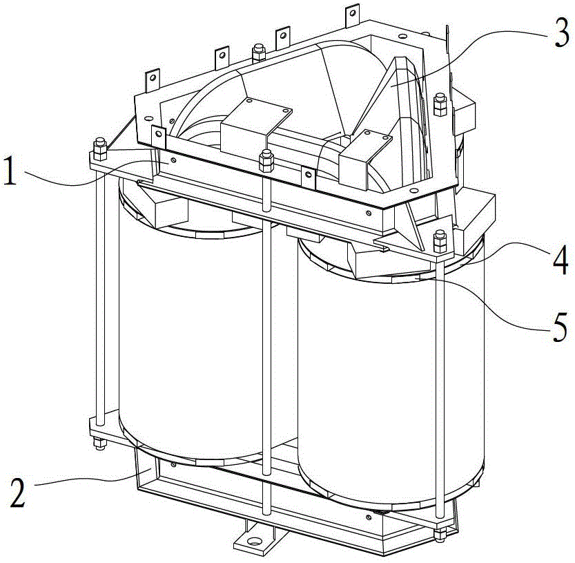
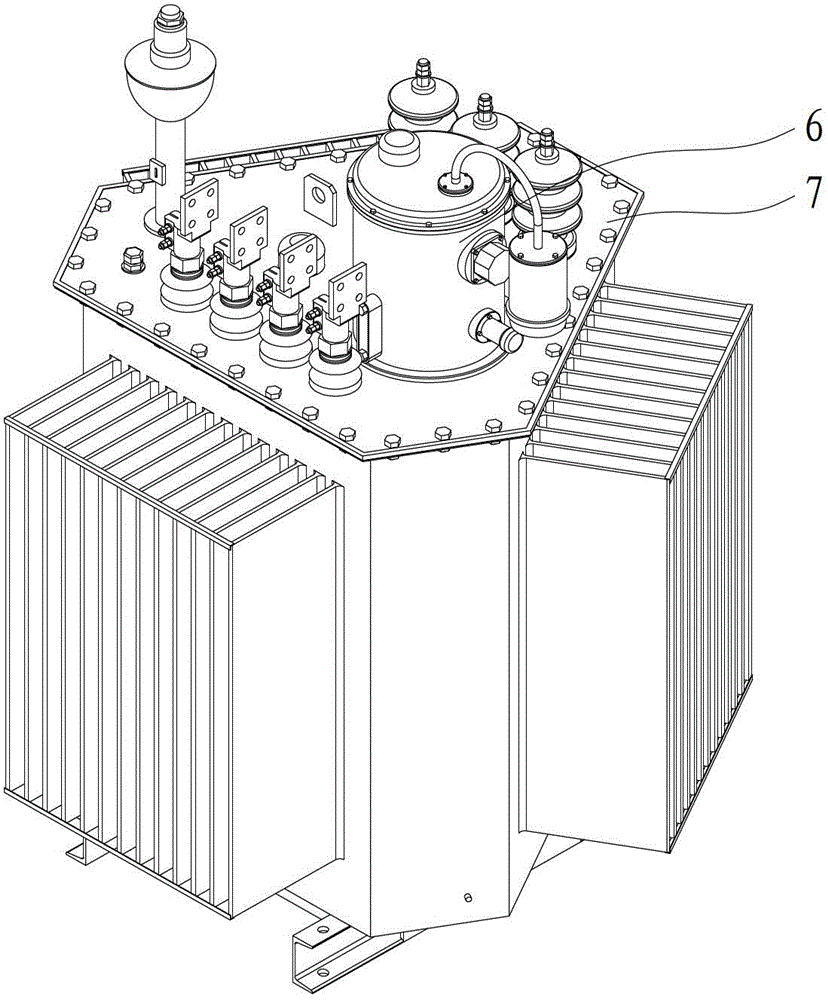
[0046] The present invention provides an energy-saving transformer with adaptive function, such as figure 1 as shown, figure 1 It is the internal structure diagram of the energy-saving transformer provided by the present invention, including: an upper clamp 1 and a lower clamp 2, a three-dimensional wound core 3 is arranged between the upper clamp 1 and the lower clamp 2, and a low-voltage winding is wound on the three-dimensional wound core 3 4 and the high-voltage winding 5, the low-voltage winding and the high-voltage winding taps are connected with a special on-load capacity adjustment switch 6, and the on-load capacity adjustment switch is installed on the fuel tank 7, such as figure 2 as shown, figure 2 It is the outline drawing of the energy-saving transformer provided by the present invention.

[0047] Through the use of...


PUM


Abstract

The invention provides an energy-saving transformer with a self-adaptation function. The energy-saving transformer comprises a three-dimensional rolled iron core. The three-dimensional rolled iron core is of a three-dimensional structure with a right triangular cross section formed by combining three single-frame iron cores; the single-frame iron cores are formed by continuously rolling an amorphous alloy magnetic permeability material in a seamless manner; a low-voltage winding and a high-voltage winding are wound on the three-dimensional rolled iron core; taps of the low-voltage winding and the high-voltage winding are respectively connected with a loaded capability regulation switch; wire turns of the low-voltage winding are connected in parallel or in series; the high-voltage winding is in triangular connection or a star-like connection; and the loaded capability regulation switch is controlled by a loaded capability regulation controller. According to the energy-saving transformer provided by the invention, the amorphous alloy energy-saving material, the single-frame iron core seamless winding technology, the energy-saving structure of the three-dimensional rolled iron core, and various automatic size and capability adjusting energy-saving technologies are organically combined to realize the zero-load consumption of the transformer to the greatest extent, so that the construction investment of a power grid and the consumption of the raw materials in an equipment manufacturing process can be reduced; and the operation security, the power supply quality and the power supply reliability of the power grid can be improved.

Description

technical field [0001] The invention relates to an energy-saving transformer in the field of electric equipment, in particular to an energy-saving transformer with an adaptive function. Background technique [0002] At present, distribution transformers with energy-saving effects continue to emerge, but the energy-saving technologies used in them are nothing more than a single application of new materials or new structures. Most of these products have only one aspect of energy-saving advantages. Performance S11 type distribution transformer and SH15 type amorphous alloy transformer made of silicon steel sheet or amorphous alloy material, or S13 type three-dimensional wound core distribution transformer manufactured by three-dimensional wound core technology, although their energy-saving effect has been greatly improved , but there is still a lot of room for further energy saving, and they cannot solve some long-standing problems in the power grid: such as 10kV power distribu...

Claims


Application Information

Patent Timeline
Patent Type & Authority Patents(China)
IPC IPC(8): H01F29/04H01F27/26H01F27/25H01F1/153H01F27/28H01H1/56H01H19/54
Inventor 韩筛根邓宏芬吴燕刘岚丁妍
Owner CHINA ELECTRIC POWER RES INST
Learn More