Disk brake

A disc brake and brake caliper technology, applied in the direction of brake type, brake components, axial brake, etc., can solve the problem of high production cost, and achieve the effects of weight reduction, simple installation, and reduction of external dimensions.

Active Publication Date: 2007-09-12
HALDEX BRAKE PROD AB
View PDF0 Cites 10 Cited by
  • Summary
  • Abstract
  • Description
  • Claims
  • Application Information

AI Technical Summary

Problems solved by technology

[0009] In order to distribute this braking force, the pressure plate comprises regular large dimensions and is heavy and thus expensive to produce
In addition, the dimensions of the pressure plate lead to a severe restriction of variability and freedom in the design of the caliper in the areas of the caliper body where increased mechanical strength occurs, especially in the transfer area between the caliper housings, where mounted actuator, and the closing vane of the caliper covering the brake disc extends outside the housing

Method used


Image

  • Disk brake
  • Disk brake
  • Disk brake

Examples


Embodiment Construction

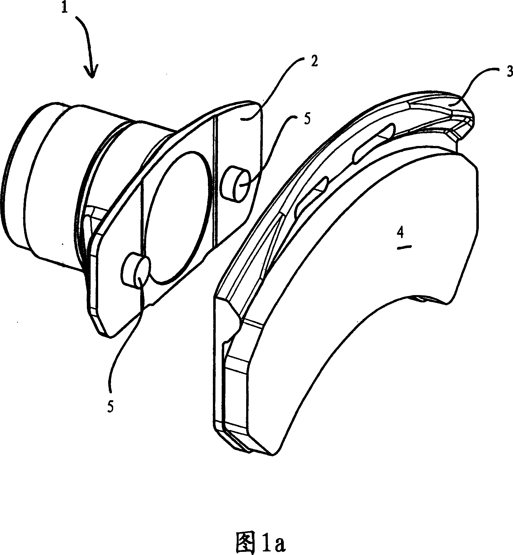
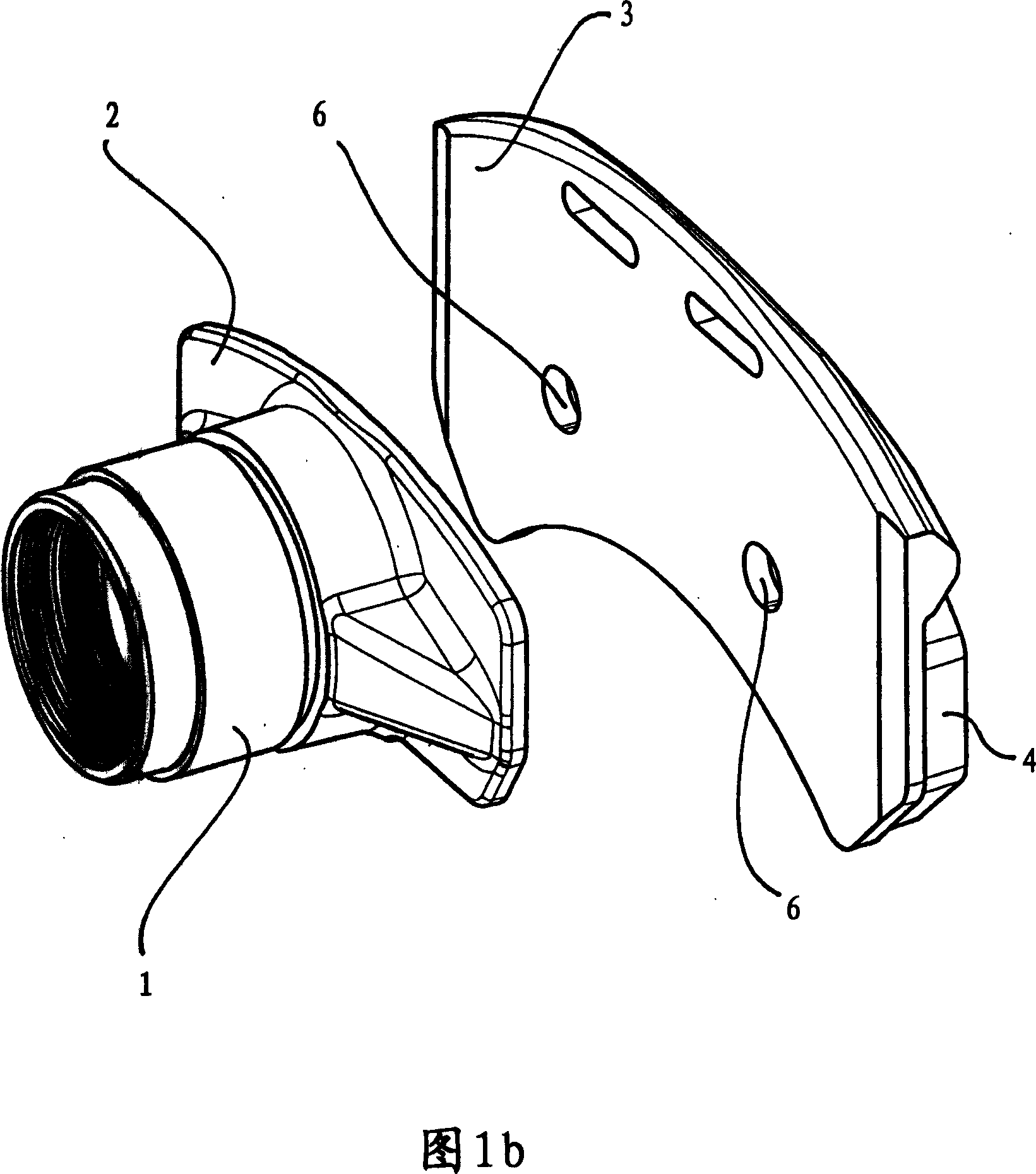
[0044] Figures 1a and 1b are examples of parts of a disc brake according to the first embodiment, including a cylindrical push rod 1 on which the pressure plate is positioned, and a brake pad on which the brake pad 4 is positioned. Holder 3. This push rod 1 is driven by a reinforcing mechanism not shown in detail here and is positioned in the brake caliper housing.

[0045] The pressure plate 2 facing the brake lining holder 3 on its surface has two pin-shaped protrusions 5 which are aligned at a distance from each other.

[0046] As can be seen in FIG. 1b, the brake lining holder 3 has a corresponding recess 6 of complementary form into which the protrusion 5 engages when assembled, preferably allowing some play.

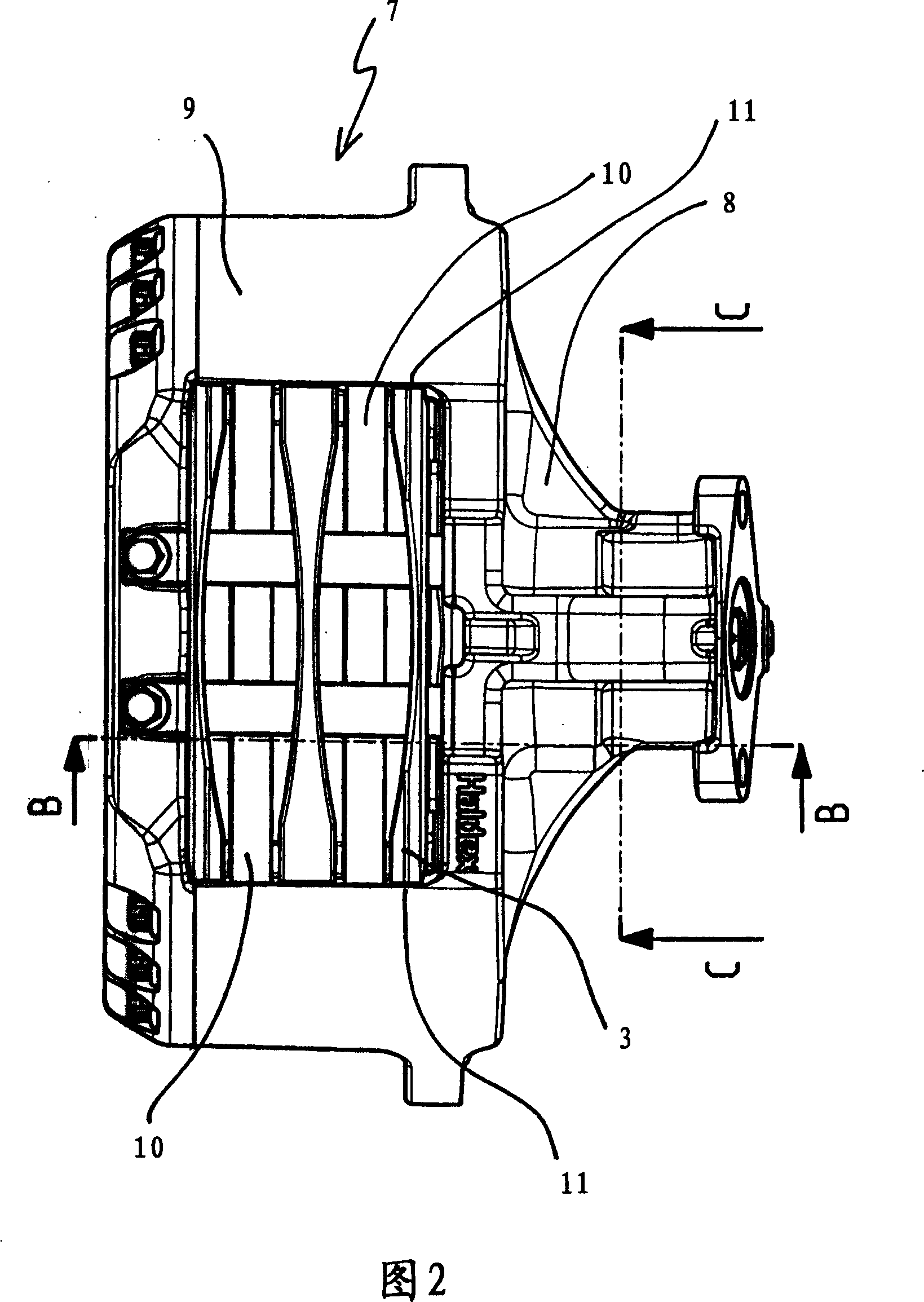
[0047] FIG. 2 shows a disc brake in top view in which the aforementioned elements are integrated.

[0048] The disc brake has a brake caliper 7 and two blades or arms 9 extending over two brake discs 10 , the brake caliper having a caliper housing 8 for accommoda...


PUM


Abstract

The present invention relates to a disk brake in which a connection is configured between a brake lining retainer and a pressure plate of a push rod in order to move the push rod by means of the brake lining retainer so that it slides axially in a brake caliper.

Description

technical field [0001] The present invention relates to disc brakes, in particular for motorcycles, and to brake lining retainers for use in such disc brakes. Background technique [0002] Most disc brake systems of all construction types share the common goal of keeping the mass and weight of the construction as low as possible on the one hand and, on the other hand, setting the components and construction in the motorcycle as low as possible Simple without compromising the functional patterns and the life of your disc brakes. [0003] In disc brakes known in the state of the art, the brake actuating mechanism is generally arranged inside the caliper housing and this mechanism comprises a reinforcing mechanism, such as an eccentrically mounted lever, and a push rod connected to the reinforcing mechanism, the The push rod can be, for example, a crossbeam, said lever driven by the pressure cylinder, which is mounted eccentrically to reinforce the braking forces induced by th...

Claims


Application Information

Patent Timeline
Patent Type & Authority Applications(China)
IPC IPC(8): F16D65/092
CPCF16D65/0979F16D55/226F16D65/0971F16D65/183F16D65/38F16D2055/007F16D2121/14F16D2125/58
Inventor G·斯滕松S·松德贝里
Owner HALDEX BRAKE PROD AB
Why Eureka
Try Eureka