

Image transfer device
A technology for transmitting devices and images, applied in optics, lenses, instruments, etc., can solve problems such as difficulty, ghosting, and poor image resolution.
- Summary
- Abstract
- Description
- Claims
- Application Information
AI Technical Summary
Problems solved by technology
Method used
Image

Examples
Embodiment Construction
[0071] Next, a first embodiment of the present invention will be described with reference to the drawings.
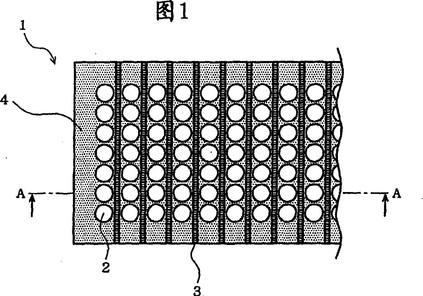
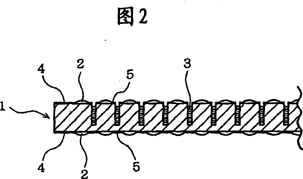
[0072] Fig. 1 is a lens plate plan view showing an erecting lens array constituting an aerial display device for a stereoscopic image and a two-dimensional image of the present invention, an image projection device to a screen, an image transmission device for imaging images on a photoelectric element and a photoreceptor, Fig. 2 is a sectional view along line A-A of Fig. 1 .
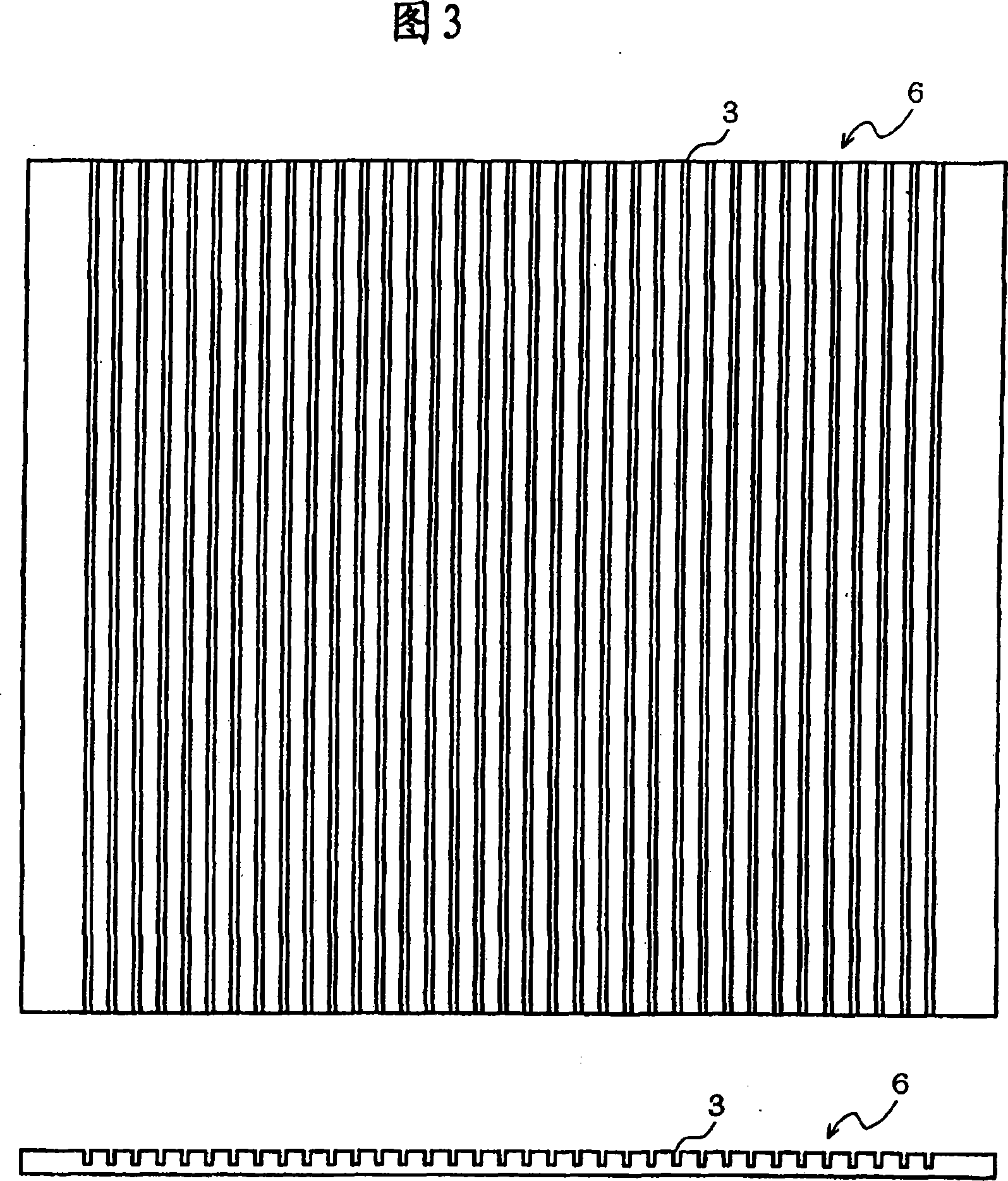
[0073] On the lens plate 1, a plurality of rectangular grooves 3 are formed at predetermined intervals in parallel to the short sides thereof. The rectangular groove 3 has a deep depth relative to the width of the opening and a high aspect ratio. Here, grooves are formed that are about four times the width of the opening and have a depth of about 60% of the thickness of the lens plate 1 . It is satisfactory that the rectangular groove 3 is formed at a depth of one-third or more of the thickness ...
PUM
 Abstract
Description
Claims
Application Information