
Position detecting apparatus, position inputting apparatus and computer

A detection device and display device technology, which is applied to the structural components of portable computers, the input/output process of calculation, and data processing, etc., can solve problems such as display failures, and achieve the effect of preventing display failures.

Active Publication Date: 2007-09-19
WACOM CO LTD
View PDF2 Cites 11 Cited by
  • Summary
  • Abstract
  • Description
  • Claims
  • Application Information

AI Technical Summary

Problems solved by technology

However, in the position detection device of the electromagnetic induction method, since the detection part requires the wiring of a plurality of detection conductors, when the detection part is arranged on the display side of the display device, there may be a problem in the array of display elements of the display device. Display failure due to moiré interference fringes etc. between the detection conductor of the detection unit

Method used


Image

  • Position detecting apparatus, position inputting apparatus and computer
  • Position detecting apparatus, position inputting apparatus and computer
  • Position detecting apparatus, position inputting apparatus and computer

Examples


Embodiment Construction

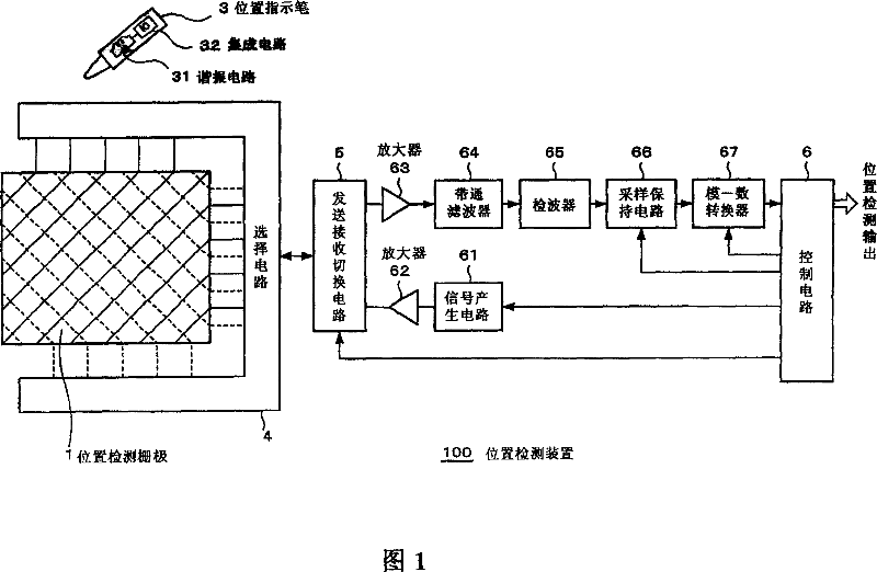
[0045] Hereinafter, the present invention will be described with reference to the drawings. FIG. 1 is a block diagram showing the configuration of an embodiment of a position detection device 100 to which the present invention is applied.

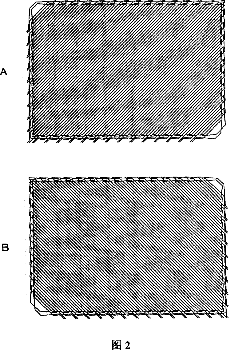
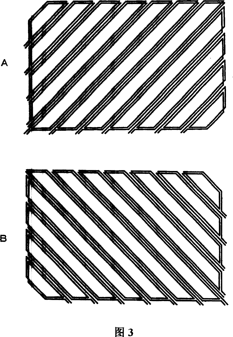
[0046] In FIG. 1 , a position detection grid 1 is schematically shown at the left end of the drawing. In addition, the display device is not shown in this FIG. 1, and the display elements in the not-shown display device are arranged in the horizontal direction and the vertical direction. Therefore, in the position detection grid 1 of FIG. 1 , the long sides of the loop coils (approximately indicated by line segments) that generate electromagnetic induction are arranged obliquely across both the horizontal direction and the vertical direction as shown in the figure. In addition, solid lines and dotted lines in the figure represent loop coils of different layers, and these are also arranged to cross each other.

[0047] And, when using this ...


PUM


Abstract

A position detecting grid 1 is provided so that the long side of a loop coil (abbreviated by a segment) performing electromagnetic induction obliquely intersects both horizontal direction and vertical direction as shown in the figure. The solid line and the broken line in the figure show loop coils of different layers, which are also provided to mutually intersect. When such a position detecting grid 1 is used, a position instructing pen 3 with a built-in resonance circuit 31, for example, is made to approach to the grid 1. According to this, the built-in resonance circuit 31 of the position instructing pen 3 is driven, for example, by an alternate magnetic field signal of a specific frequency transmitted from the grid 1, and the resonance signal thereof is received again by the grid 1.

Description

technical field [0001] The present invention relates to a position detection device, a position input device, and a computer, which are suitable for directly inputting position information from a display device, for example. Specifically, when the display device and the position detection device are combined together, display failure does not occur. Background technique [0002] For example, in a position detection device provided with a display device, when the electromagnetic induction method is used, the position detection device is disposed inside the display device in a conventional structure (for example, refer to Patent Document 1). [0003] In addition, in a position detection device using an electrostatic coupling method, in order to reduce moiré interference fringes generated when the detection conductor is provided on the display side of the display device, various methods have been devised to form the detection electrode into a zigzag shape (for example, refer to...

Claims


Application Information

Patent Timeline
Patent Type & Authority Applications(China)
IPC IPC(8): G06F3/046
CPCG06F3/046G06F1/1616G06F1/1637G06F3/047G06F3/03545G06F1/1643G06F3/0412
Inventor 伊藤雅充
Owner WACOM CO LTD
Learn More