Integrated ventilator nasal trigger and gas monitoring system

a technology of gas monitoring system and ventilator, which is applied in the field of medical devices, can solve the problems of inability to complete a full respiratory cycle, inability to measure at the y-piece or in the expiratory limb, and inadvertent compression of the face mask

Active Publication Date: 2007-12-11
GENERAL ELECTRIC CO
View PDF12 Cites 52 Cited by
  • Summary
  • Abstract
  • Description
  • Claims
  • Application Information

AI Technical Summary

Benefits of technology

[0010]An additional aspect of the nasal cannula and control system of the present invention comprises carbon dioxide sampling and monitoring by the control system with samples taken via the nasal cannula from the patient's nostrils. The sampling creates a steady state signal upon which the patient's respiratory effort signal rides in determining the detection of a patient's spontaneous breath attempt. Therefore, the present invention provides an efficient combination of carbon dioxide sampling and patient ventilation triggering from a sample taken from the patient airway.

Problems solved by technology

These difficulties may be pathological in nature or may be due to the fact that a patient is too weak or sedated to independently perform proper respiration functions.
Often, the patient may be spontaneously attempting to breath, but not able to complete a full respiratory cycle.
In prior systems that utilize a non-invasive ventilation (NIV) mask for patient ventilation and also monitor CO2 levels in the expired patient gases, leaks within the system cause diluting effects, thereby making CO2 measurements at the Y-piece or in the expiratory limb difficult.
This false identification would be due to the increased pressure in the face mask, resulting from the inadvertent compression of the face mask.
Such a misinterpretation results in asynchrony between the ventilator and the patient's respiratory efforts, ultimately reducing the assistance provided to the patient.
While leaks can occur anywhere in the circuit, a common location for leaks is between the patient / breathing circuit interface and the patient, which is typically where the face mask meets the patient's face.

Method used


Image

  • Integrated ventilator nasal trigger and gas monitoring system
  • Integrated ventilator nasal trigger and gas monitoring system
  • Integrated ventilator nasal trigger and gas monitoring system

Examples


Embodiment Construction

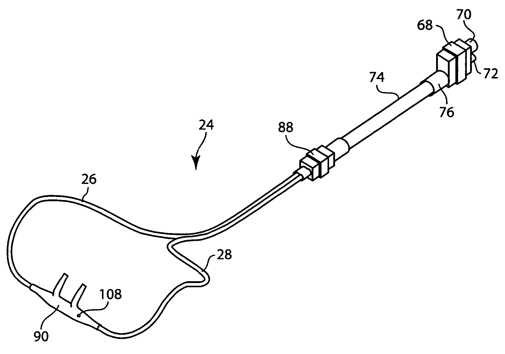
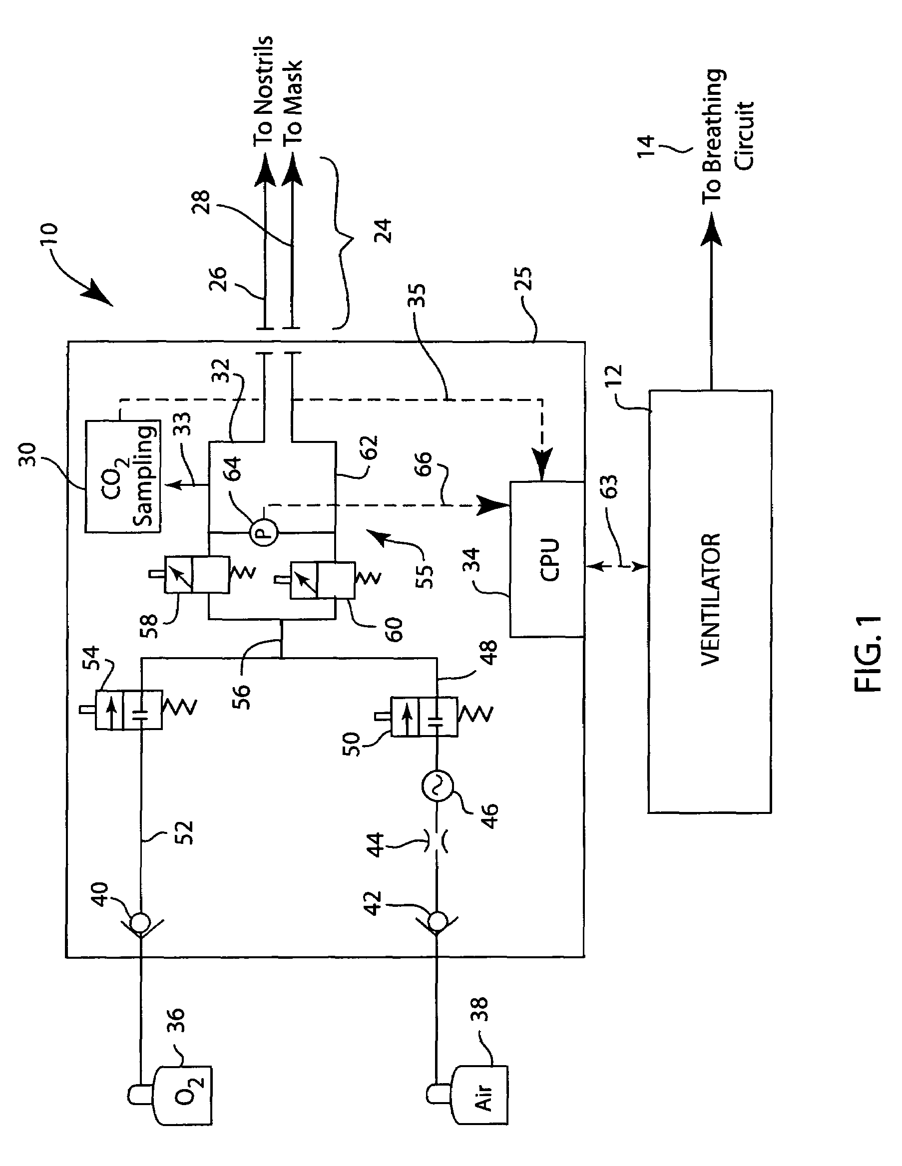
[0020]Referring first to FIG. 1, a nasal cannula control system 10 is shown as used with a positive pressure ventilator 12. Although a positive pressure ventilator 12 is shown, it should be understood that the ventilator 12 could be of any type, such as an anesthesia, ICU or transport ventilator. Additionally, although the nasal cannula control system 10 is shown separate from the ventilator 12, the nasal cannula control system 10 could be incorporated directly into the ventilator 12.

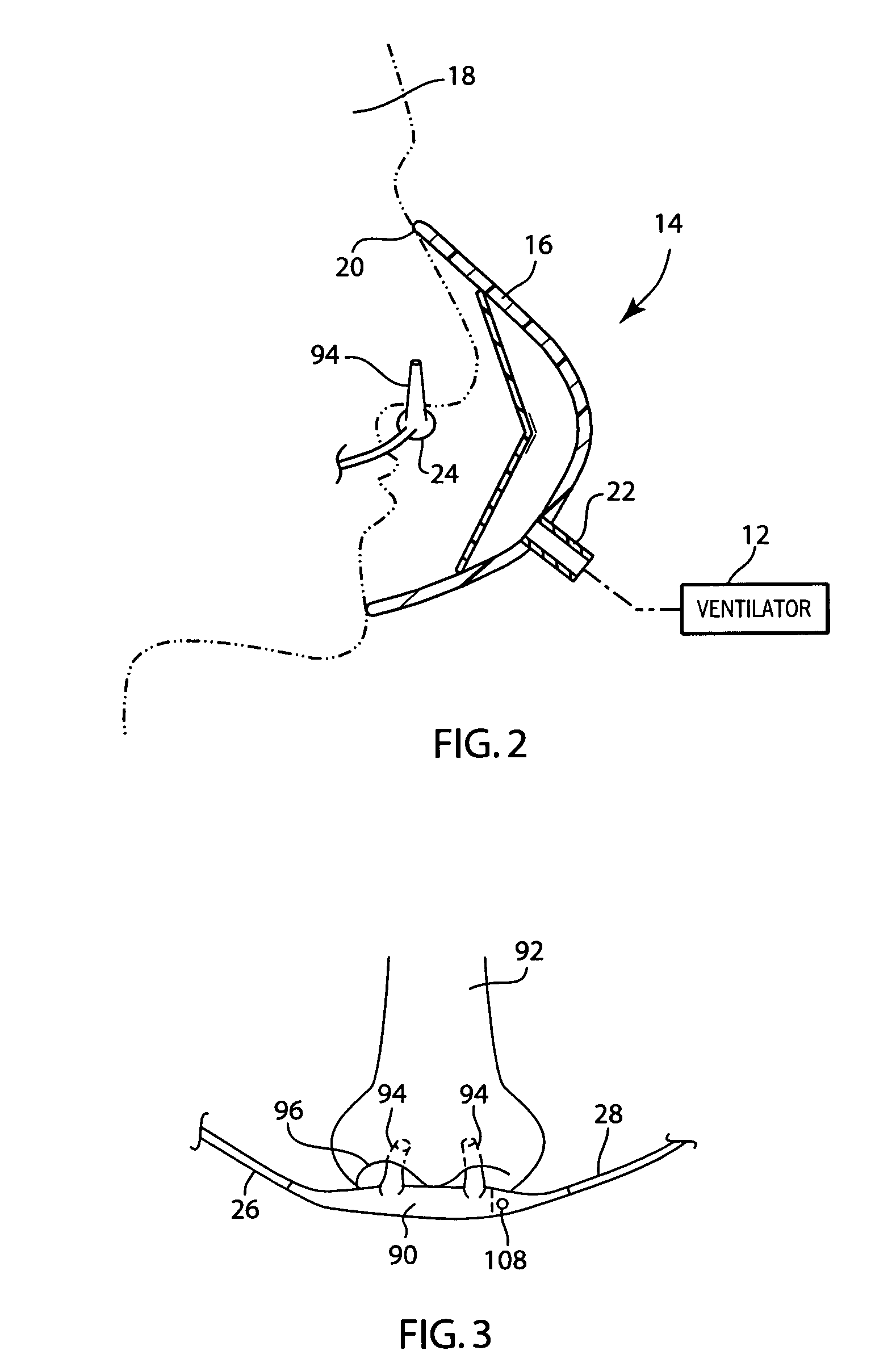
[0021]The ventilator 12 delivers a supply of ventilation gas to a patient breathing circuit 14 to provide mechanical ventilation of the patient. In the embodiment of the invention shown in FIG. 2, the patient breathing circuit 14 includes a non-invasive ventilation (NIV) breathing mask 16 that is used to deliver gases to the patient 18. As illustrated, the breathing mask 16 covers both the nose and mouth of the patient 18 and forms a seal 20 with the patient along the outer peripheral edges of the breat...


PUM


Abstract

An arrangement and method for detecting spontaneous respiratory effort of a patient receiving ventilatory support by a breathing circuit. The nasal cannula control system includes a nasal cannula assembly having two distinct lumens. A different pressure sensor is positioned to detect the pressure difference between each of the two lumens, thereby determining the differential pressure from within the patient's nostrils and within a breathing mask. The nasal cannula control system includes a gas sampling system such that the amount of a monitored gas discharged or exhaled by the patient can be monitored using the same nasal cannula assembly used to generate the differential pressure signal.

Description

FIELD OF THE INVENTION[0001]The present invention relates to a medical device for providing medical gases to a patient. More specifically, the present invention relates to a nasal cannula control system that may provide supplemental medical gas to a patient while also performing triggering of ventilation support and the monitoring of an exhaled gas from a patient, such as carbon dioxide.BACKGROUND OF THE INVENTION[0002]Patients that have respiratory difficulties often must be placed on a mechanical ventilator. These difficulties may be pathological in nature or may be due to the fact that a patient is too weak or sedated to independently perform proper respiration functions. Often, the patient may be spontaneously attempting to breath, but not able to complete a full respiratory cycle. In these cases, mechanically assisted ventilation is provided. In mechanically assisted ventilation, a combination of pressure and / or flow sensors detects a patient's breath attempt. This detection tr...

Claims


Application Information

Patent Timeline
Patent Type & Authority Patents(United States)
IPC IPC(8): A61M11/00
CPCA61B5/0836A61B5/097A61B5/6819A61M16/06A61M16/0666A61M16/085A61M16/0672A61M2230/432A61M2016/0021A61M2230/005A61M16/0858
Inventor ACKER, JARON M.THAM, ROBERT Q.TZANETAKIS, ANDREAS
Owner GENERAL ELECTRIC CO
Why Eureka
Try Eureka