Electromagnetic coil

A technology of electromagnetic coil and lead wire, applied in the direction of electromagnet, valve details, engine components, etc., can solve the problem of no variable resistance device, no variable resistance device electromagnetic coil, etc., to achieve reliable sealing, simple placement, reliable The effect of sealing and fixing

Active Publication Date: 2007-09-19
ZHEJIANG SANHUA INTELLIGENT CONTROLS CO LTD
View PDF1 Cites 4 Cited by
  • Summary
  • Abstract
  • Description
  • Claims
  • Application Information

AI Technical Summary

Problems solved by technology

However, the electromagnetic coils of the existing structure, including the patent document JP-9-106911, neither involve the setting of the variable resistance device nor how to reasonably place the variable resistance device so that the electromagnetic coil can fully play its role

Method used


Image

  • Electromagnetic coil
  • Electromagnetic coil
  • Electromagnetic coil

Examples


Embodiment Construction

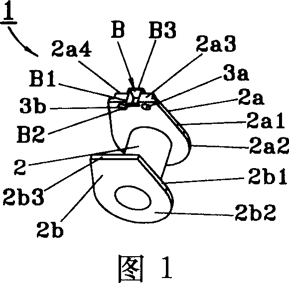
[0027] Fig. 1 is a perspective view of a bobbin 1 of an electromagnetic coil, which includes a hollow circular cylindrical winding core 2 and a pair of parallel flange-shaped parts 2a and 2b fixed at both ends of the winding core 2; the winding core 1 The collar-like parts 2a, 2b are integrally formed by synthetic resin, such as injection molding, and the resin material is polybutylene terephthalate, unsaturated polyester resin, phenolic resin and the like.

[0028] The collar-shaped parts 2a, 2b include arc-shaped parts 2a2, 2b2 and protruding parts 2a1, 2b1 formed by extending from the arc-shaped parts to one side.

[0029] The protruding portions 2a1, 2b1 have end surfaces 2a3, 2b3, respectively, and a wide portion 2a4 is formed in the center of one end surface portion 2a3, and a bucket-shaped depression B is formed in the wide portion 2a4.

[0030] The bucket-shaped depression B has an opening B1 of the end surface 2a3, a cut-in step B2 is formed inside the collar 2a, and ...


PUM


Abstract

An electromagnetic coil includes a winding core and a pair of jaw-like portions which are arrange at two ends of the winding core and are in parallel, thereby a winding portion of a winding is formed between the jaw-like portions, a lead is connected to the winding, the winding is envelopped by a synthetic resin which at least envelops the lead portion; the coil is characterised in that each jaw-like portion includes an arc-like portion and projecting portions extending from the arc-like portion to a side, wherein one projecting portion is provided with a positioning structure for positioning the lead. In the electromagnetic coil with this structure, when the lead is contacted with electrical members such as the winding and the like, movement of the lead when sealing the synthetic resin can be effectively prevented because the lead can be positioned by the positioning structure provided on the projecting portion, the winding and an inner end of the lead can be reliably sealed and fixed, and an electromagnetic coil with electrical members provided compactly can be obtained.

Description

technical field [0001] The present invention relates to an electromagnetic control valve, an electromagnetic solenoid or an electromagnetic coil of a four-way switch valve for a refrigeration cycle, particularly relating to the placement of components and electrical components connected to the coil. Background technique [0002] Electromagnetic control valves, electromagnetic solenoids for refrigeration cycles, or electromagnetic coils for four-way switching valves for refrigeration cycles are used to convert electric power into magnetic force to change the working state of the valve, and the change of the working state of the valve may be the limit position Changes, such as the opening or closing of the medium circulation pipeline, may also be the degree of maintenance of a working state, such as the size of the opening of the medium circulation pipeline. [0003] A common electromagnetic coil includes a winding core and a pair of flange-shaped parts...

Claims


Application Information

Patent Timeline
Patent Type & Authority Applications(China)
IPC IPC(8): H01F7/06F16K31/06
Inventor 张胜昌胡梅宴
Owner ZHEJIANG SANHUA INTELLIGENT CONTROLS CO LTD
Why Eureka
Try Eureka