Check patentability & draft patents in minutes with Patsnap Eureka AI!

Rotating generator for vehicle

A technology for power generation devices and vehicles, applied in electromechanical devices, electrical components, electric components, etc., can solve the problems of high cost, incompatible energy economy, and large fuel consumption.

Inactive Publication Date: 2007-09-19
魏永彬
View PDF0 Cites 4 Cited by
  • Summary
  • Abstract
  • Description
  • Claims
  • Application Information

AI Technical Summary

Problems solved by technology

[0002] Usually, the electricity used in the vehicle is generated by the vehicle power plant, and its power plant relies on the added fuel, such as gasoline or diesel, to generate electricity. This traditional power generation method consumes a lot of fuel and costs a lot. , does not conform to today's energy economy; at the same time, the power in many places in the vehicle is not fully utilized, such as the turning force generated when the tire rotates during the running of the vehicle, etc., the present invention is based on this consideration , designed a rotating power generation device in the vehicle, which can greatly reduce fuel consumption, and the cost is low, which is in line with the principle of economy

Method used


Image

  • Rotating generator for vehicle
  • Rotating generator for vehicle
  • Rotating generator for vehicle

Examples


Embodiment Construction

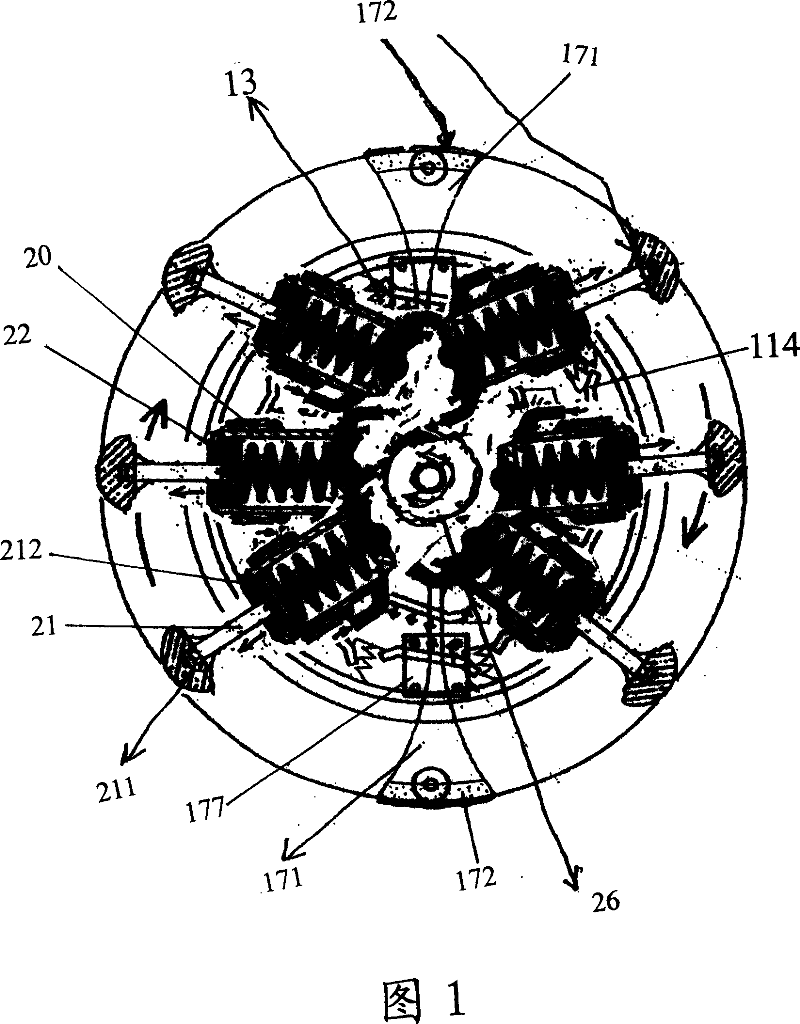
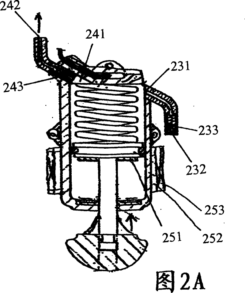
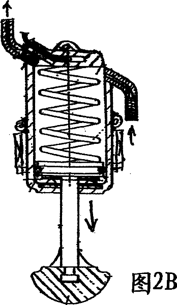
[0015] As shown in Figures 1 to 4, the present invention provides a rotating power generation device in a vehicle, which includes a rim rotor seat body 12 and a power generation seat body 11 mounted on a transmission shaft 10 through a bearing 151, wherein the power generation seat body The body 11 is provided with an upper insulating sheet 111, a silicon steel sheet 113, a lower insulating sheet 112 and a casing 14 in sequence through bolts, a stator magnet sheet 114 is arranged on the silicon steel sheet 113, and a Copper wire coil 13 is arranged, and described copper wire coil is set corresponding to stator magnet piece 114, and described housing 14 is installed on the transmission shaft 10 through bearing 152; Described rim rotor base 12 is provided with cavity, and in cavity A rotor magnet piece 123 is placed inside, and a magnet piece upper cover 121 and a lower cover 122 are arranged on the rim rotor base body 12, and the upper cover 121 and the lower cover 122 are fixed...


PUM


Abstract

The present invention relates to a rotation power generation device for vehicle which comprises a wheel rim rotor base seat and a power generation base seat mounted on a drive shaft, wherein the power generation base seat is arranged with an upper insulation plate, a silicon steel plate, a lower insulation plate and a casing, the silicon steel plate has a stator magnet plate and a copper wire winding provided thereon; the wheel rim rotor base seat is provided with a rotor magnet plate, meanwhile, the wheel rim rotor base seat is fixed on one end of the rotor spindle the other end of which has a gear fixed thereon; two poles are arranged opposite to each other in tyre diameter direction, one end of the pole is arranged with a rubber block, and the other end is arranged with a gear rack the direction of which is parallel to the pole. The gear rack is engaged with the gear. Power is generated by a power generation device comprised by the wheel rim rotor base seat and the power generation base seat. The power generation device further includes a set of air cylinder mechanisms fixed on the vehicle wheel hub by which gas can be transferred to a pneumatic motor arranged on the wheel axis so as to drive the power generation device to generate power by the pneumatic motor.

Description

technical field [0001] The invention relates to a rotary power generation device in a vehicle, in particular to a rotary power generation device which utilizes the rotary power generated when the tire rotates. Background technique [0002] Usually, the electricity used in the vehicle is generated by the vehicle power plant, and its power plant relies on the added fuel, such as gasoline or diesel, to generate electricity. This traditional power generation method consumes a lot of fuel and costs a lot. , does not conform to today's energy economy; at the same time, the power in many places in the vehicle is not fully utilized, such as the turning force generated when the tire rotates during the running of the vehicle, etc., the present invention is based on this consideration , a rotating power generation device in a vehicle is designed, which can greatly reduce fuel consumption, and the cost is low, which is in line with the principle of economy. Contents of the invention ...

Claims


Application Information

Patent Timeline
IPC IPC(8): H02K35/02H02K7/18
Inventor 魏永彬
Owner 魏永彬
Features
  • R&D
  • Intellectual Property
  • Life Sciences
  • Materials
  • Tech Scout
  • Unparalleled Data Quality
  • Higher Quality Content
  • 60% Fewer Hallucinations
Learn More