Temperature indicator

A temperature indicator and indication technology, applied to thermometers, instruments, and thermometers with physical/chemical changes, etc., can solve problems such as user erroneous impressions, complex temperature indicators, and temperature indicators that cannot give any information, etc., to achieve manufacturing and handle the effect easily

Inactive Publication Date: 2007-09-19
KONINK PHILIPS ELECTRONICS NV
View PDF2 Cites 11 Cited by
  • Summary
  • Abstract
  • Description
  • Claims
  • Application Information

AI Technical Summary

Problems solved by technology

A disadvantage of a temperature indicator of the kind described in US 6,396,027 B1 is that it is complex and requires the correct cooperation between several components to accurately warn the user of high temperatures
For example, a broken indicator light can give the user the false impression that the iron is cold when in fact it is hot
Furthermore, such temperature indicators do not give any information as to which part of the surface is hot

Method used


Image

  • Temperature indicator
  • Temperature indicator
  • Temperature indicator

Examples


Embodiment Construction

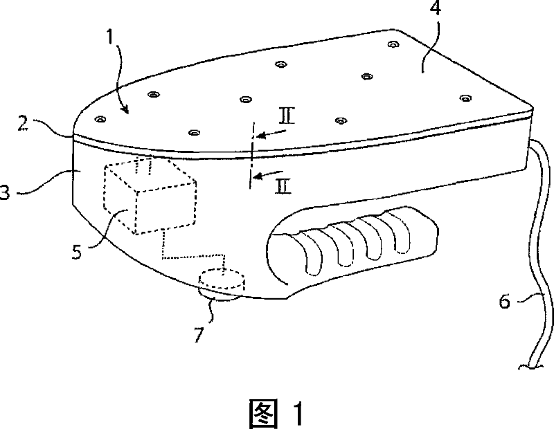
[0038] Fig. 1 schematically illustrates a temperature indicator 1 in a first embodiment of the invention. The temperature indicator 1 covers the entire bottom surface 2 of the iron 3 . The temperature indicator 1 includes a light-emitting electrochemical cell 4 and an AC power source 5 suitable for driving the light-emitting electrochemical cell 4 with low-frequency alternating current. An AC power supply 5 is connected to the mains power system of the iron 3 (not shown in FIG. 1 ) and supplies the luminescent electrochemical cell 4 with AC power throughout the time the cable 6 of the iron 3 is connected to an external power source. An AC frequency modulator 7 may optionally be included in the temperature indicator 1 to fine-tune the temperature at which light should begin to glow, as will be described in more detail below.

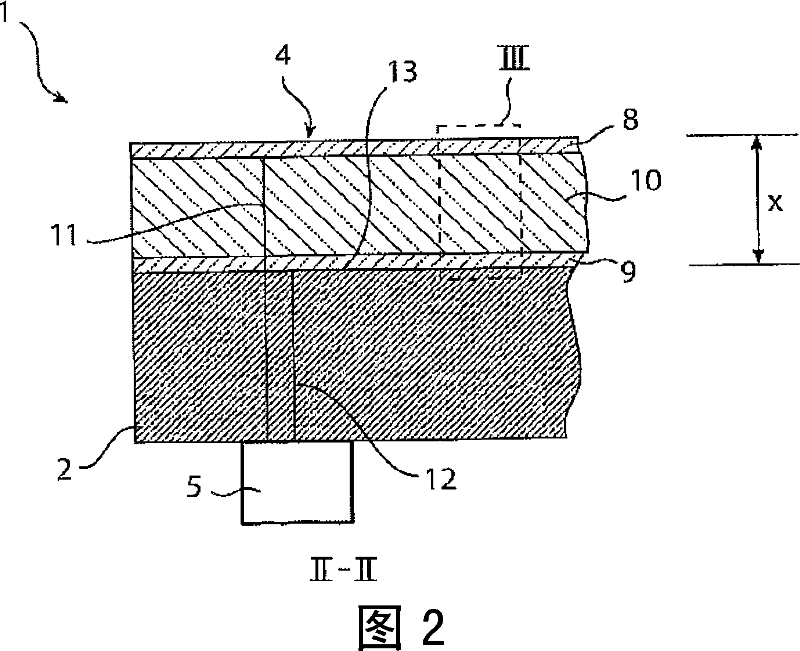
[0039] FIG. 2 is a cross-sectional view illustrating a light-emitting electrochemical cell 4 having the shape of a thin laminate on the bottom surface 2...


PUM

PropertyMeasurementUnit
thicknessaaaaaaaaaa
thicknessaaaaaaaaaa

Abstract

A temperature indicator (1) for indicating a high temperature at a surface (13) comprises a light-emitting electrochemical cell (4) having a first electrode (8), a second electrode (9) and a light-emitting layer (10) being sandwiched between the two electrodes (8, 9). The light-emitting layer (10) comprises a matrix and ions being movable in the matrix, the mobility of said ions in said matrix being temperature dependent. A power source (5) is adapted for driving the light-emitting cell (4) with an AC voltage. The frequency of the AC voltage is tuned in such a way that, above a certain temperature level, the ions move fast enough in the matrix to provide a sufficient charge gradient in the light-emitting electrochemical cell (4) for the light-emitting electrochemical cell (4) to emit light before the AC power source (5) shifts the polarity of the voltage.

Description

technical field [0001] The present invention relates to a temperature indicator adapted to be placed on a surface for providing a visual indication of the temperature of the surface. [0002] The invention also relates to a method of forming a temperature indicator adapted to be placed on a surface for providing a visual indication of the temperature of the surface. Background technique [0003] High temperatures are involved when used in many electrical appliances. Examples of these appliances are irons, water heaters, electric stoves, ovens, frying pans, toasters, Washington cookie cutters, and the like. To avoid injury, such as burns, to people using these appliances, indicators are needed to tell people using these appliances that they are hot and must be careful. This high temperature indication is usually achieved with a temperature sensor, a control unit connected to this temperature sensor, and a warning light that lights up on the control unit when the sensor dete...

Claims


Application Information

Patent Timeline
Patent Type & Authority Applications(China)
IPC IPC(8): G01K11/12
CPCG01K11/12
Inventor 爱德华·J.·迈耶尔拉尔夫·库尔特
Owner KONINK PHILIPS ELECTRONICS NV
Why Eureka
Try Eureka