

Loudspeaker
A technology of loudspeaker and magnetic circuit, applied in the field of loudspeakers, can solve the problems of vibration plate 37 amplitude motion restriction, air resistance increasing, etc.
- Summary
- Abstract
- Description
- Claims
- Application Information
AI Technical Summary
Problems solved by technology
Method used
Image

Examples
Embodiment approach 1
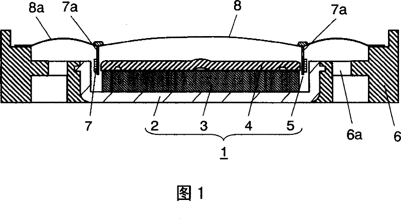
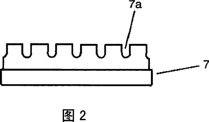
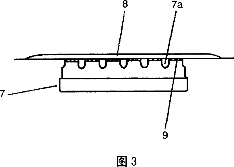
[0034] Embodiment 1 will be described below using FIGS. 1 to 3 . The magnetic circuit 1 is formed by laminating and coupling a disk-shaped magnet 3 and a plate 4 in a pot-shaped yoke 2 . Thus, an annular magnetic gap 5 is formed. The frame 6 made of resin couples the magnetic circuit 1 at the center. Vent holes 6 a are provided in the frame 6 . Voice coil 7 is movably fitted in magnetic gap 5 formed in magnetic circuit 1 . A plurality of notches 7a are provided at the upper end of the bobbin constituting the voice coil 7 . Vibration plate 8 is bonded to voice coil 7 at the center, and its outer periphery is bonded to the periphery of frame 6 . Edge portion 8 a is integrally provided on the periphery of diaphragm 8 . The outer periphery of the edge portion 8 a is joined to the peripheral edge of the frame 6 . In addition, voice coil 7 and diaphragm 8 are bonded using adhesive 9 . Furthermore, as shown in FIG. 3 , the bonding is performed so that the adhesive 9 does not c...
Embodiment approach 2
[0037] The communication structure of the present embodiment is different from the communication structure described in the first embodiment in which the gap formed between the rear surface of the diaphragm of the speaker and the inside of the voice coil communicates with the outside. The rest of the configuration is the same as that of Embodiment 1, so the same reference numerals are assigned to the same parts and detailed description thereof will be omitted, and only different parts will be described.
[0038] Description will be made using FIGS. 5 to 6B. A plurality of holes 10 a are provided on the periphery of the bottom surface of the pot-shaped yoke 10 . Thus, the magnetic circuit 12 in which the annular magnetic gap 11 is formed is formed.
[0039] In the speaker according to the present embodiment configured in this way, the gap formed between the back surface of the diaphragm 8 and the inside of the voice coil 13 communicates with the outside through the hole 10 a p...
Embodiment approach 3
[0042] The communication structure of the present embodiment is different from the communication structure described in the first embodiment in which the gap formed between the rear surface of the diaphragm of the speaker and the inside of the voice coil communicates with the outside. The rest of the configuration is the same as that of Embodiment 1, so the same reference numerals are assigned to the same parts and detailed description thereof will be omitted, and only different parts will be described.
[0043] Description will be given using FIGS. 8 to 9B . A plurality of notches 14 a are provided on the side wall of the pot-shaped yoke 14 . Thus, the magnetic circuit 16 in which the annular magnetic gap 15 is formed is formed.
[0044] In the speaker according to the present embodiment configured in this way, the gap formed between the back surface of the diaphragm 8 and the inside of the voice coil 13 communicates with the outside through the notch 14 a provided on the si...
PUM
 Abstract
Description
Claims
Application Information