Refrigeration system

A refrigeration device and refrigerant technology, applied in the direction of refrigerators, refrigeration and liquefaction, lighting and heating equipment, etc., can solve the problems of reducing cooling capacity, adjusting evaporators, and no longer being able to control, so as to improve reliability, stabilize control, The effect of preventing freezing

Active Publication Date: 2007-09-26
DAIKIN IND LTD
View PDF1 Cites 17 Cited by
  • Summary
  • Abstract
  • Description
  • Claims
  • Application Information

AI Technical Summary

Problems solved by technology

However, there is the following problem in the above-mentioned refrigeration device: the cooling capacity of the evaporator can only be adjusted within the capacity control range of the compressor
For example, when the compressor is at minimum capacity, there is a problem that it can no longer be controlled in the case where the cooling capacity needs to be further reduced

Method used


Image

  • Refrigeration system
  • Refrigeration system
  • Refrigeration system

Examples


Embodiment Construction

[0038] Hereinafter, embodiments of the present invention will be described in detail based on the drawings.

[0039] "Embodiment 1 of the Invention"

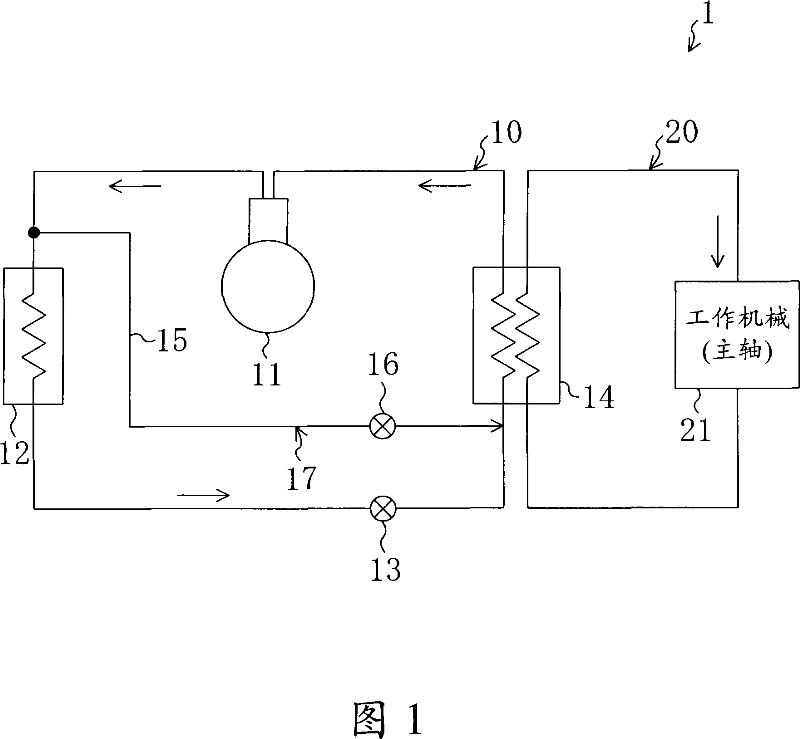
As shown in Fig. 1, the refrigerating device (1) of the first embodiment is equipped with a refrigerant circuit (10), and the refrigerant circuit (10) is connected to a cooling system as a rotating part for cooling a working machine, that is, a main shaft (21). A cooling oil circuit (20) using one side circuit in which oil circulates as a heat medium cools the cooling oil to a specific temperature. The refrigerant circuit (10) is a closed circuit formed by sequentially connecting a variable capacity compressor (11), a condenser (12), an expansion mechanism (13) and an evaporator (14), and the above-mentioned cooling oil circuit (20) Connected to the above evaporator (14).

[0040] The above-mentioned compressor (11) includes an inverter compressor (11) capable of controlling the operating capacity according to the inverter cont...


PUM


Abstract

Disclosed is a refrigeration system wherein a hot gas bypass circuit (15) is provided for allowing a refrigerant discharged from a compressor (11) to flow bypassing at least a condenser (12) and a expansion valve (13) and a flow control valve (16) is arranged in the hot gas bypass circuit (15).

Description

technical field [0001] The present invention relates to a refrigeration device comprising a refrigerant circuit in which a variable capacity compressor, a condenser, an expansion mechanism, and an evaporator are sequentially connected, and the evaporator is connected to a utilization-side circuit of a heat medium circulation. Background technique [0002] Hitherto, as shown in Japanese Patent Laid-Open No. 2001-165058, for example, this refrigeration device is connected to a cooling oil circuit (using one side circuit) that circulates cooling oil for cooling the main shaft of a machine tool as a heat medium. It is used by those in the industry for a specific temperature. In this refrigerating apparatus, the temperature of the cooling oil is controlled by controlling the variable capacity of the converter as a compressor. [0003] (The problem to be solved by the invention) However, the above-mentioned refrigerating apparatus has the following problem: the cooling capacity...

Claims


Application Information

Patent Timeline
Patent Type & Authority Applications(China)
IPC IPC(8): F25B1/00
Inventor 寺田祐一铃木克己山口贵弘笠原伸一米森强
Owner DAIKIN IND LTD
Why Eureka
Try Eureka