
Secure sensor chip

A sensor chip, sensor technology, applied in the direction of safety communication devices, instruments, transmission systems, etc.

Inactive Publication Date: 2007-09-26
KONINKLIJKE PHILIPS ELECTRONICS NV
View PDF0 Cites 7 Cited by
  • Summary
  • Abstract
  • Description
  • Claims
  • Application Information

AI Technical Summary

Problems solved by technology

Additional challenge-response pairs can be formed by measuring at different frequencies or using different voltage modulation amplitudes

Method used


Image

  • Secure sensor chip
  • Secure sensor chip
  • Secure sensor chip

Examples


Embodiment Construction

[0047] A number of embodiments for carrying out the method according to the invention will be described below with reference to the accompanying drawings.

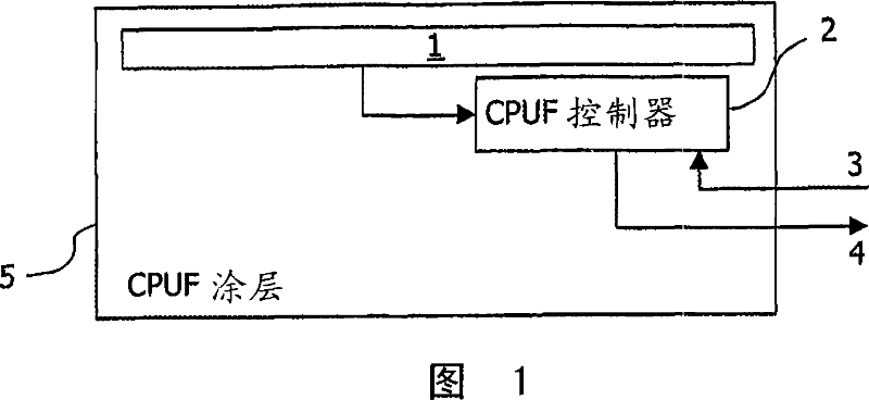
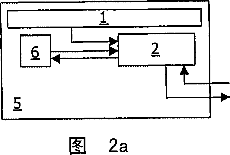
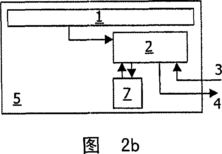
[0048] One embodiment of the invention is implemented by coating the chip and the microcontroller (which is referred to herein simply as the controller) with a Physically Random Function (PUF) layer, preferably in the form of a coated PUF. A schematic view of this embodiment is shown in Fig. 1, which shows a sensor chip according to an embodiment of the present invention. In this figure, the sensor chip is indicated by numeral 1. The sensor chip is controlled by a microcontroller 2 (called CPUF controller), which is connected to the external environment through input lines 3 and output lines 4 . These input and output lines are the only connection to the external environment. Both the sensor chip and the microcontroller 2 are embedded within the CPUF coating 5 . In the illustrated example, it is assumed that the sensor ...


PUM


Abstract

A method and device for providing a secure sensor chip (1) for recording digital information regarding at least one physical parameter, wherein the recording later can be verified with respect to its authenticity, whether the at least one physical parameter was indeed recorded by the specified chip (1) or not, wherein this is accomplished by providing the sensor chip (1) with a Controlled Physical Random Function (CPUF) in the form of a coating (5) and wherein both the sensor chip (1) and a micro controller (2) controlling all digital inputs (3) and outputs (4) of the sensor chip are both embedded in the CPUF coating (5).

Description

technical field [0001] The invention relates to the realization of a sensor chip for recording data or data sequences, which sensor chip is then verified as to the authenticity of the data, ie whether the subsequently used data form the original recorded data. As an example, when using digital cameras and digital video cameras in which images or video sequences are recorded, the authenticity of the data forming subsequently reproduced images or video sequences may be checked against the original recorded data. Background technique [0002] Digital cameras have been on the market for quite some time. A digital camera is only one aspect of digital photography. Although you need a camera to capture images, there are many different tools and devices including the general concept of digital photography. In fact, all that is needed to develop a complete digital photography solution is a system of products that work together to help users capture, store, manage and display photos...

Claims


Application Information

Patent Timeline
IPC IPC(8): G07C9/00H01L23/00G06F21/60G06F21/73G06F21/86G10L17/00
CPCH01L2924/0002G06F21/73H04L9/3278G07C9/00158H01L23/576G06F21/60G06F21/86H04L2209/805H01L2924/3011G07C9/37H01L2924/00H04N5/92H01L23/00G07C9/00G08B13/06
Inventor G·J·施里詹P·T·图尔斯
Owner KONINKLIJKE PHILIPS ELECTRONICS NV
Learn More