High-frequency heating power supply device

A high-frequency heating and equipment technology, applied in microwave heating, electric/magnetic/electromagnetic heating, electrical components, etc., can solve the problem of current drop and achieve the effect of increasing the margin

Active Publication Date: 2007-09-26
PANASONIC CORP
View PDF3 Cites 9 Cited by
  • Summary
  • Abstract
  • Description
  • Claims
  • Application Information

AI Technical Summary

Problems solved by technology

On the contrary, since the current I1 becomes far away from the resonant frequency when the current I1 is close to the high frequency, the current of the second coil winding of the leakage transformer drops

Method used


Image

  • High-frequency heating power supply device
  • High-frequency heating power supply device
  • High-frequency heating power supply device

Examples


no. 1 approach

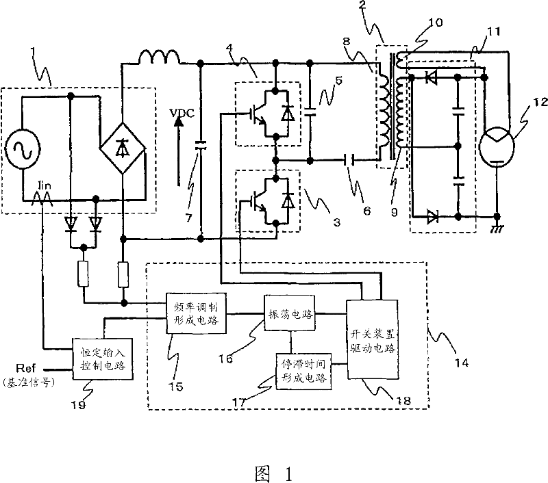
[0074] FIG. 1 is a diagram showing a circuit configuration for driving a magnetron according to the present invention. DC power supply 1, flux leakage transformer 2, first semiconductor switching element 3, second semiconductor switching element 4, first capacitor 5, second capacitor 6, third capacitor 7, drive control IC unit 14, full-wave voltage multiplier rectification The circuit 11 and the magnetron 12 constitute the overall circuit. Since the overall circuit is the same as that shown in FIG. 12, a description thereof will be omitted.

[0075] In the drive control IC unit 14 for driving the semiconductor switching elements 3 and 4, the frequency modulation forming circuit 15 forms a frequency modulation waveform using a resistance-divided waveform according to the voltage of a commercial power supply. The frequency modulation forming circuit 15 performs feedback control receiving a signal from the constant control circuit 19 to obtain the above-mentioned required input ...

no. 2 approach

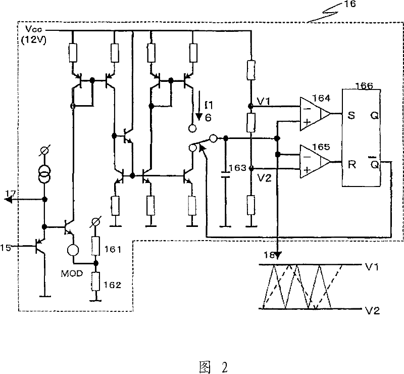
[0080] FIG. 4 is an exemplary diagram illustrating in detail the frequency modulation forming circuit shown in FIG. 1 . The fixed voltage obtained in the resistors 151 and 152 becomes the upper limit according to the voltage division waveform after rectifying the commercial power supply (aspects 3 and 8). Fig. 6(a) shows the frequency modulation waveform at this time. The waveform is divided according to the rectified voltage of the commercial mains indicated by the dotted line, and the upper value is given as realized. Subsequently, when diodes 158 and 159, and resistors 155, 156, and 157 are provided to the upper clamp shown in FIG. The voltage varies with certain curves instead of fixed values ​​(aspect 9). Fig. 6(b) shows the curve indicated by the solid line. Furthermore, in order to determine the upper limit as a variable value instead of a fixed value, either increase or decrease according to the voltage information of the commercial power source is possible (aspects...

no. 3 approach

[0082] FIG. 7 is a diagram showing an example of the frequency modulation forming circuit 15 shown in FIG. 1 . The lower limit value is limited to a fixed value given from the resistors 153 and 154 according to the voltage division waveform after rectifying the commercial power supply. In this case, lower limit clamping means that the lower limit value corresponds to the lowest frequency limit (facets 4, 5, 12 and 16). FIG. 9( a ) shows the frequency modulation waveform in this case, and represents the lower limit indicated by the solid line (lower limit corresponding to the lowest frequency) from the commercial power rectified voltage division waveform indicated by the broken line. Subsequently, when the resistors are provided to the lower limit clamp shown in FIG. 8, the frequency modulation waveform can be formed as a curve with some variation from the reference values ​​obtained in resistors 153 and 154, instead of a fixed value (facet 13). Fig. 9(b) shows the curve indi...


PUM


Abstract

There is provided a high-frequency heating power supply device for driving a magnetron such as a microwave oven. It is possible to provide a frequency modulation method for suppressing high-frequency current generated by high-frequency switching operation. When supplying a DRIVE signal for driving a first semiconductor switching element (3) and a second semiconductor switching element (4), the inverter operation frequency for each commercial power supply phase is supplied with a frequency difference (inclination) of phase 0 to 90 degrees by a triangular wave generation circuit in an oscillation circuit (16). The modulation waveform for frequency modulation control is formed by setting the upper limit clamp, the lower limit clamp, and the lowest value equivalent to the lowest frequency by the frequency modulation generation circuit (15) according to the commercial power supply division waveform after rectification. By optimally combining these, generation of higher harmonic current is suppressed while forming a frequency modulation waveform capable of absorbing various irregularities such as an inverter main circuit parts constant and a power source (Vcc) of drive control IC unit (14).

Description

technical field [0001] The present invention relates to control for suppressing harmonic current components in the field of high-frequency heating equipment such as a microwave oven that performs a dielectric heating process by driving a magnetron. Background technique [0002] Power sources used in cooking appliances based on high-frequency heating, such as microwave ovens used at home, have been required to be small in size and light in weight because of the characteristics of cooking appliances. Preferably, there is less space for the power supply to transport it easily and increase the cooking space in the kitchen. For this reason, microwave ovens are becoming smaller and lighter, and manufactured at a lower cost by using switching power supplies. As a result, the power supply outputs a current waveform containing many harmonic components resulting from the switching operation of the power supply. In addition, microwave ovens consume as much as 2000 watts in order to s...

Claims


Application Information

Patent Timeline
Patent Type & Authority Applications(China)
IPC IPC(8): H05B6/66H02M7/48H02M7/538
CPCH05B6/685Y02B40/143Y02B40/00
Inventor 守屋英明末永治雄酒井伸一城川信夫木下学
Owner PANASONIC CORP
Why Eureka
Try Eureka