

Control apparatus for a switched reluctance motor
a control apparatus and reluctance motor technology, applied in the direction of electrical equipment, control systems, electronic commutators, etc., can solve the problems of insufficient effect of apparatus distortion of interlinkage magnetic flux waveform of coil, and many harmonic components, so as to reduce harmonic core losses and noise of sr motor, moderate changes in the flux linkage of coil, and the effect of reducing harmonic core losses and nois
- Summary
- Abstract
- Description
- Claims
- Application Information
AI Technical Summary
Benefits of technology
Problems solved by technology
Method used
Image

Examples
first embodiment
[0060]A control apparatus for a switched reluctance (SR) motor as a vehicle prime mover in accordance with a first embodiment of the present invention will be described more fully hereinafter with reference to the accompanying drawings.
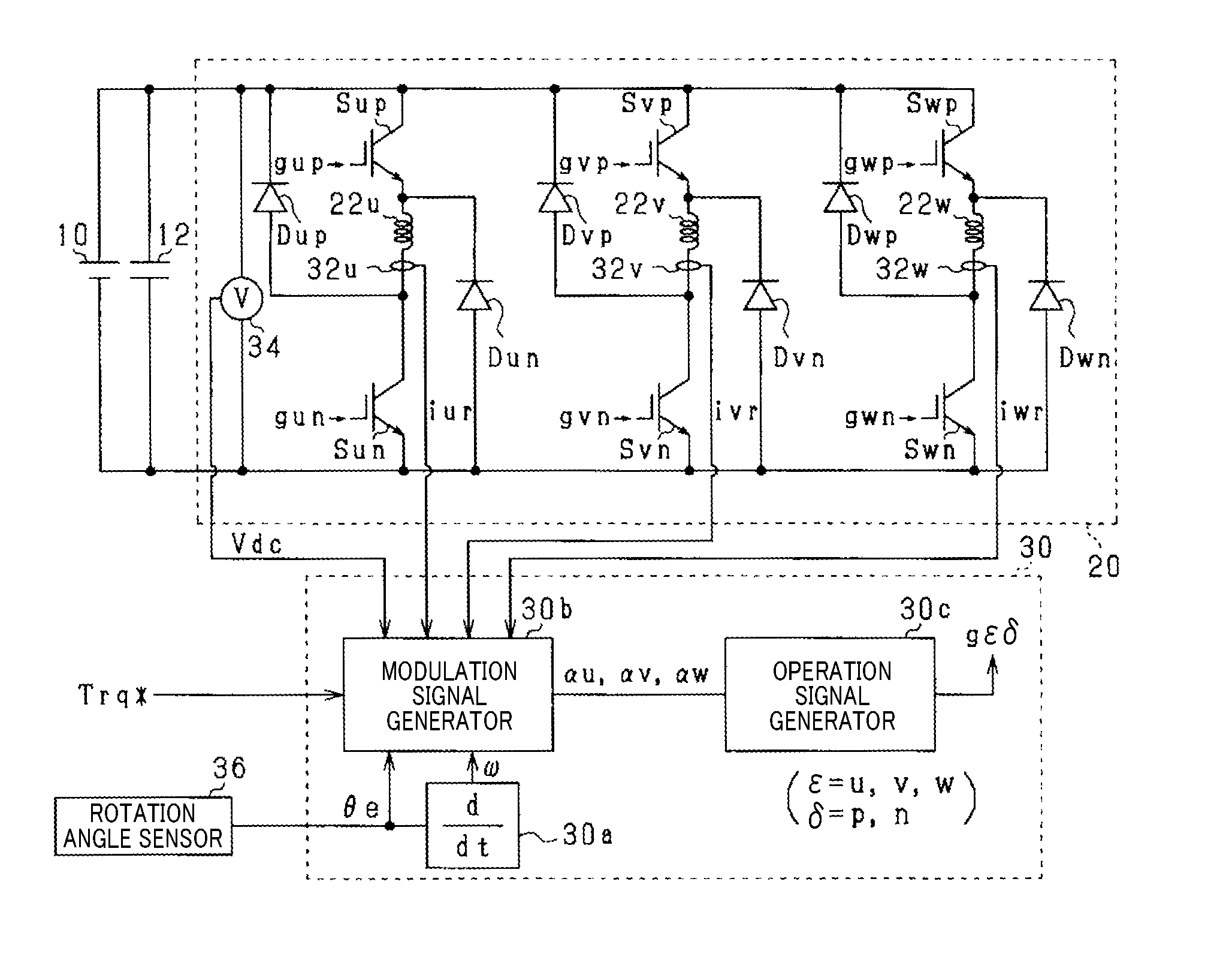
[0061]As shown in FIG. 1, a high-voltage battery 10, as a DC power supply, is a secondary battery having a terminal voltage of 100V or more (e.g., 288V), such as a lithium-ion secondary battery, a nickel-metal-hydride secondary battery or the like.
[0062]The high-voltage battery 10 is electrically connected to a power conversion circuit 20 via a smoothing capacitor 12. The power conversion circuit 20 is electrically connected to a vehicle-mounted motor generator as a vehicle prime mover. The motor generator is a SR motor. More specifically, in the present embodiment, a three-phase SR motor having a U-phase coil 22u, a V-phase coil 22v and a W-phase coil 22w is used as the SR motor. The power conversion circuit 20 includes a series connection of a U-pha...
second embodiment
[0110]There will now be explained a second embodiment of the present invention. Only differences of the second embodiment from the first embodiment will be explained.
[0111]In the present embodiment, as shown in FIG. 13B, a region where the voltage control process described above is performed is limited with respect to the command torque Trq* and the electrical angular speed ω that is a rotation speed of the rotor of the SR motor. In FIG. 13B, the maximum torque is denoted by Tmax.
[0112]FIG. 14 shows a flowchart of a process of limiting a region where the voltage control process is performed. This process is performed in the control apparatus 30 repeatedly every predetermined time interval.
[0113]First, in step S30, it is determined whether the command torque Trq* is equal to or less than a prescribed torque Tβ and the electrical angular speed ω is equal to or less than a prescribed speed ωβ.
[0114]If it is determined in step S30 that the command torque Trq* is equal to or less than th...
third embodiment
[0123]There will now be explained a third embodiment of the present invention. Only differences of the third embodiment from the first embodiment will be explained.
[0124]In the present embodiment, a modulation signal αε is generated so as to compensate for a voltage drop due to the presence of a resistance r of the coil 22ε. FIG. 15 shows an example of a voltage drop caused by the presence of a resistance r of the U-phase a coil 22u.
[0125]FIG. 16 shows a flowchart of a process of generating the modulation signal in accordance with the present embodiment. This process is performed in the operation signal generator 30c of the control apparatus 30 repeatedly every predetermined time interval.
[0126]In FIG. 16, the same operations as in FIG. 5 are assigned the same numbers.
[0127]First, in step S10a, in addition to the command torque Trq*, the electrical angle θe and the electrical angular speed ω, an ε-phase detected current iεr and a DC voltage Vdc detected by the voltage sensor 34 are...
PUM
 Abstract
Description
Claims
Application Information