Series fan and its flow guide structure

A tandem, fan technology, applied in non-variable-capacity pumps, components of pumping devices for elastic fluids, machines/engines, etc., can solve the problems of reduction, flow field disorder, low fan blade work efficiency, etc.

Active Publication Date: 2007-10-10
DELTA ELECTRONICS INC
View PDF0 Cites 7 Cited by
  • Summary
  • Abstract
  • Description
  • Claims
  • Application Information

AI Technical Summary

Problems solved by technology

[0006] However, since the two fans rotate in the same direction, for the rotor blade 12b of the second fan 10B, its rotation direction X is in the same direction as the partial component of the inlet airflow V3, so the relative speed of the rotor blade 12b to the airflow is reduced, resulting in The performance of the second fan 10B is not good. Even though the fan body has a stator blade design, the purpose of the stator blade design is to increase the performance of the fan body, but it cannot completely guide the airflow leaving the fan body (because the performance of the single unit is completely guided) will reduce), so that the work of the rear fan is often only 30% to 80% of that of the front fan, and if the number of series connection is more, the work efficiency of the rear fan blades will be lower, and the purpose of series connection cannot be achieved
[0007] In addition, when fans are connected in series, the two moving blades 12a, 12b are too close to each other, which causes the flow field at the junction of the outlet of the first fan 10A and the inlet of the second fan 10B to be quite turbulent, resulting in a significant increase in noise when the two fans are connected in series , resulting in application limitations

Method used


Image

  • Series fan and its flow guide structure
  • Series fan and its flow guide structure
  • Series fan and its flow guide structure

Examples


Embodiment Construction

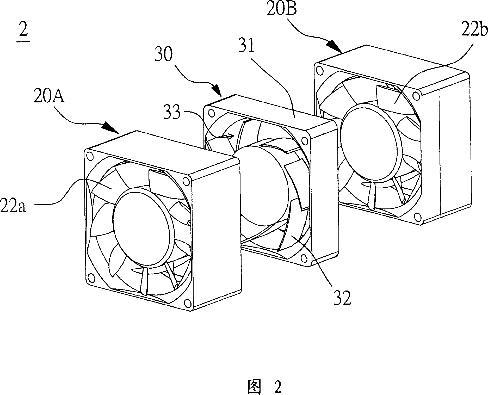
[0036] Please refer to FIG. 2 , which is a schematic diagram of a serial fan according to a preferred embodiment of the present invention. The serial fan 2 at least includes a first fan 20A, a second fan 20B and a flow guiding structure 30 . The second fan 20B is connected in series with the first fan 20A, and the flow guiding structure 30 is disposed between the first fan 20A and the second fan 20B. The air guide structure 30 is used to guide the air flow from the first fan 20A, and the air flow angle when entering the second fan 20B is parallel to the axial direction, so as to increase the air volume and air pressure of the serial fan 2 . The first fan 20A and the second fan 20B are axial flow fans, and the flow guide structure 30 and the serial fan 2 are independent, and can be combined or separated from each other by, for example, free clamping, locking or bonding.

[0037] Please refer to Figure 3A and Figure 3B at the same time, Figure 3A is a schematic cross-sectional ...


PUM


Abstract

The present invention discloses a series-connected type fan. It at least includes a first fan, a second fan and a flow-guiding structure. Said first fan and second fan are series-connected, and the flow-guiding structure is placed between first fan and second fan. Said flow-guiding structure can be used for guiding the air flow flowed out from said first fan and making said air flow be fed into second fan so as to raise air volume and air pressure of said series-connected type fan.

Description

technical field [0001] The invention relates to a fan, in particular to a serial fan and a flow guiding structure which can increase the air volume and pressure of the airflow and reduce the noise during operation. Background technique [0002] With the continuous improvement of the performance of electronic components, heat dissipation device or cooling system has become one of the indispensable equipment in the current electronic components, because if the heat energy generated by electronic components is not properly dissipated, the performance will deteriorate at least, and the serious It will cause burning of electronic components. Heat sinks are even more important for microelectronic components, such as integrated circuits, because with the increase in integration and the advancement of packaging technology, the area of ​​integrated circuits is continuously shrinking, and the accumulated per unit area The heat energy is relatively higher, so heat dissipation devices ...

Claims


Application Information

Patent Timeline
Patent Type & Authority Applications(China)
IPC IPC(8): F04D29/54F04D29/16
Inventor 许家铭张楯成黄文喜
Owner DELTA ELECTRONICS INC
Why Eureka
Try Eureka