(MTC) Flow sensor with flow signal amplifying function
A technology of flow sensor and amplification function, which is applied in the field of flow sensor with flow signal amplification function, which can solve the problems of too small flow signal and no signal, and achieve the effects of expanding the scope of application, improving accuracy, and not being easy to block
- Summary
- Abstract
- Description
- Claims
- Application Information
AI Technical Summary
Problems solved by technology
Method used
Image

Examples
Embodiment 1
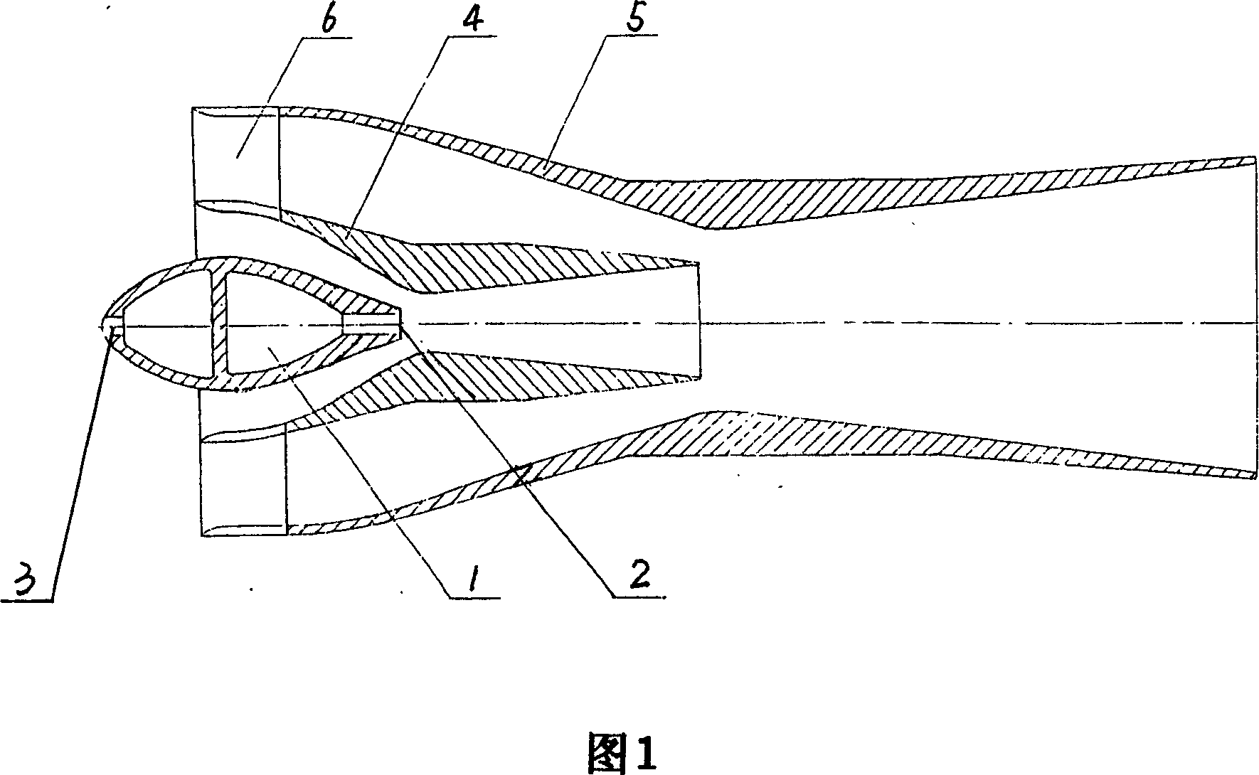
[0021] Embodiment 1, see Fig. 1. The present invention includes a measuring stick 1 that adopts the trailing edge of the static pressure tube to take pressure, such as the measuring stick described by the applicant in ZL03262719. Assemblies, the assembly includes a thin-waisted inner sleeve 4 and an outer sleeve 5 connected by 6, the inlet side of the inner sleeve 4 and the outer sleeve 5 are all tapered bowl-shaped tubes, and the inlet end is cylindrical, and There is an arc-shaped chamfer on the inner side of the end, and a fixed notch on the end, which is connected to one side of the static pressure tube of the sensor, and the static pressure taking port 2 is located on the axis of the inner casing 4 Thin waist; the outlet side of the inner sleeve 4 and the outer sleeve 5 are tapered, the inner sleeve 4 is arranged on the inlet side of the outer sleeve 5, and the inlet end faces of the inner sleeve 4 and the outer sleeve 5 are flush , the outlet end of said inner casing 4 ...
Embodiment 2
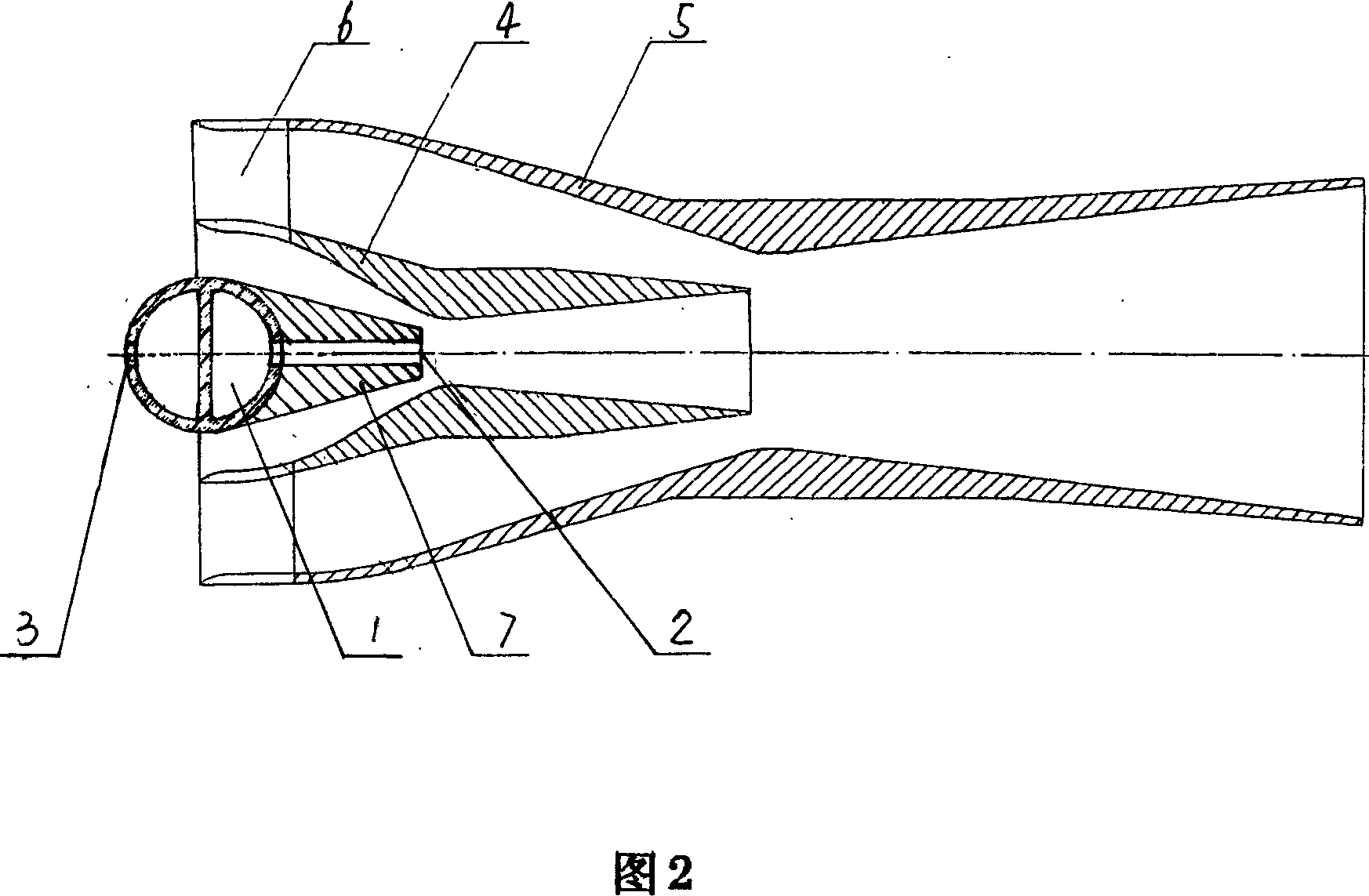
[0023] Embodiment 2, see Fig. 2. If the static pressure tapping port of the measuring rod used is not at the lowest flow rate designed by the signal amplification component, only one diversion nozzle needs to be added at this time. The pressure tubes are nested and matched to form a streamlined outer surface, and the pressure-taking hole in the diversion nozzle 7 communicates with the static pressure-taking port 2 on the trailing edge of the static pressure tube. The size of the diversion nozzle 7 is determined according to the shape of the trailing edge of the static pressure tube of the measuring rod, as long as the static pressure taking port 2 is extended to the thin waist of the inner casing 4.
Embodiment 3
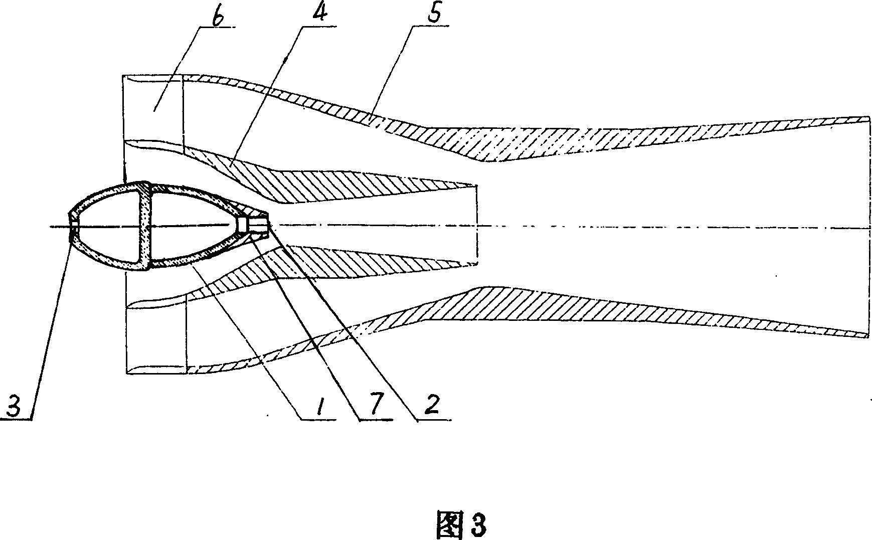
[0024] Embodiment 3, see Fig. 3. The nozzle in this embodiment is nested with the static pressure tube of the measuring rod 1 to form a streamlined outer surface, and the static pressure tapping port 2 is extended to the narrow waist of the inner casing 4 .
[0025] Referring to Fig. 4, when the present invention is used, the total pressure tap and the static pressure tap of the measuring rod are arranged correspondingly or alternately, and a flow signal multistage amplifying device is installed on each static pressure tap. For example, 4 to 51 total pressure taps are set on the measuring stick; 3 to 50 static pressure taps are set, and a flow signal multi-stage amplification device can be installed on each static pressure tap.
PUM
 Abstract
Description
Claims
Application Information
 - R&D
- Intellectual Property
- Life Sciences
- Materials
- Tech Scout
- Unparalleled Data Quality
- Higher Quality Content
- 60% Fewer Hallucinations
Browse by: Latest US Patents, China's latest patents, Technical Efficacy Thesaurus, Application Domain, Technology Topic, Popular Technical Reports.
© 2025 PatSnap. All rights reserved.Legal|Privacy policy|Modern Slavery Act Transparency Statement|Sitemap|About US| Contact US: help@patsnap.com