Ion engine device

An engine and ion technology, applied in electrical components, power plant types, generators/motors, etc., can solve problems such as inability to popularize, and achieve the effect of convenient and free flight, wide application range, and reduced volume

Inactive Publication Date: 2007-10-10
许晓春
View PDF0 Cites 0 Cited by
  • Summary
  • Abstract
  • Description
  • Claims
  • Application Information

AI Technical Summary

Problems solved by technology

[0002] At present, common flying vehicles include airplanes, helicopters, etc., but they must have professional driving skills, long runways or special venues, so they cannot be popularized

Method used


Image

  • Ion engine device
  • Ion engine device

Examples


Embodiment

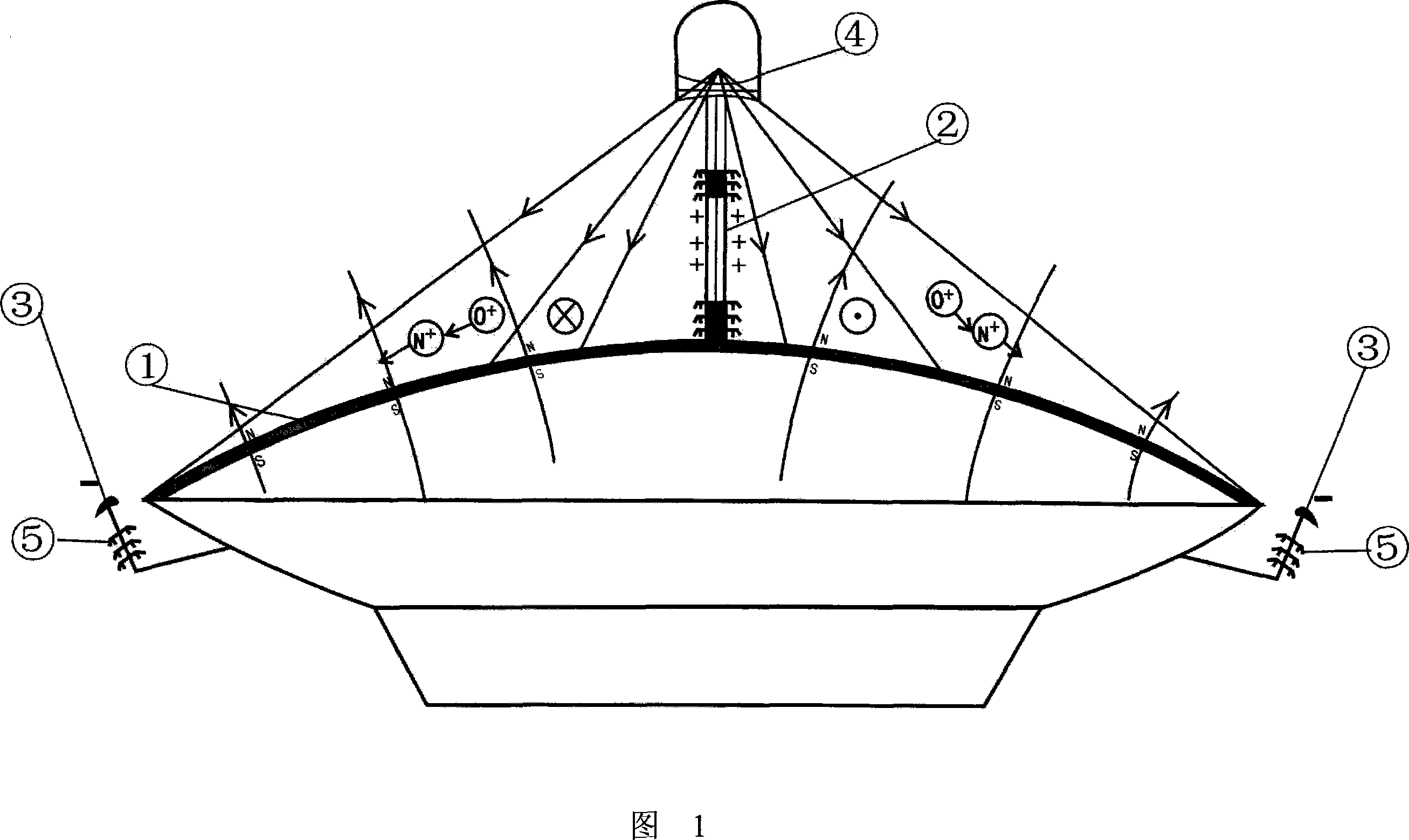
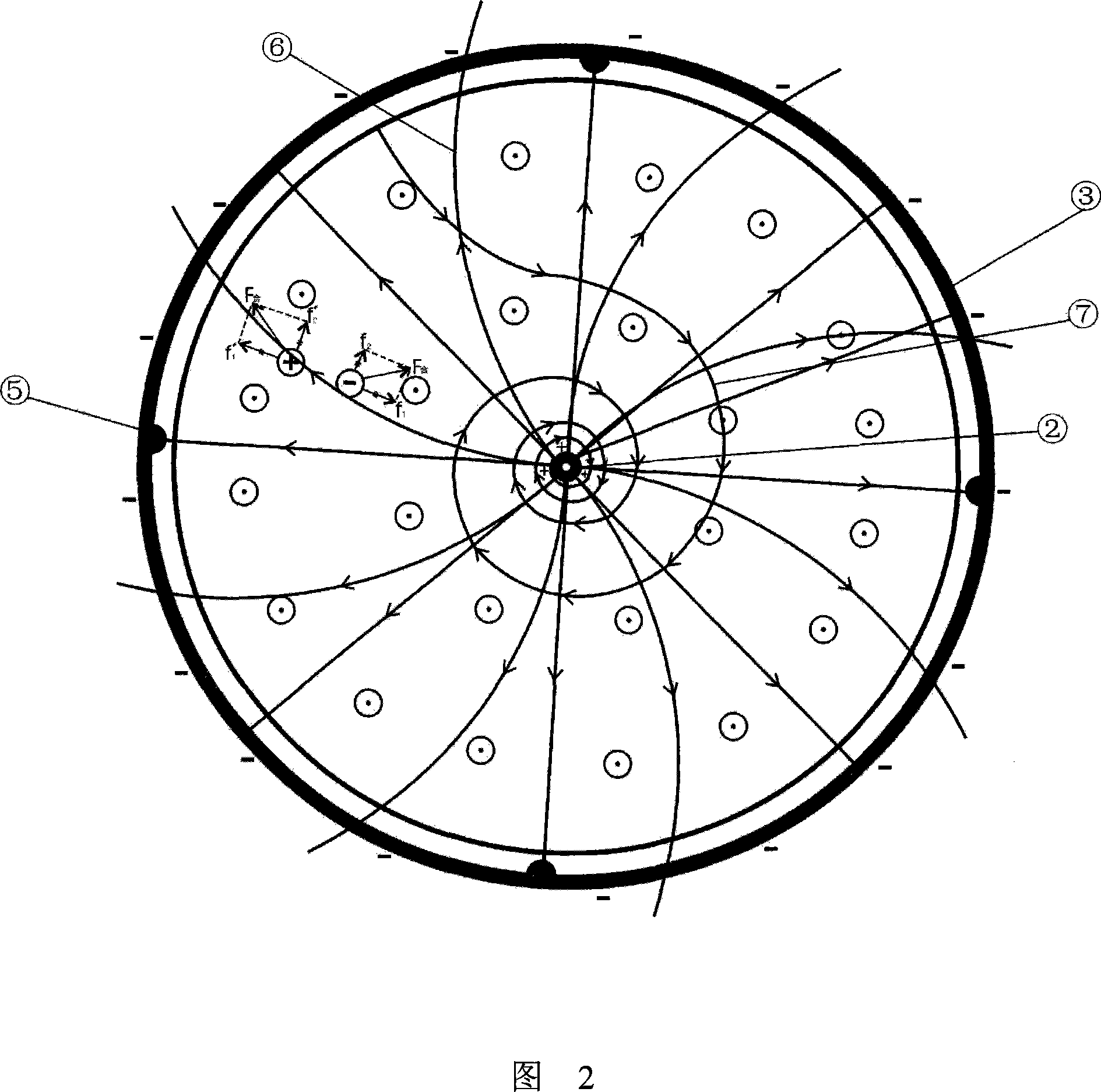
[0017] Embodiment: as shown in Fig. 1, Fig. 2, a kind of ion engine device comprises engine loam cake 1 and power supply device, and upward positive pole central axis 2 is installed on engine loam cake 1, and the upper end of positive pole central axis 2 is provided with wavelength A laser 4 that can cover the entire engine top cover 1 and can ionize nitrogen and oxygen; the edge of the engine top cover 1 is provided with a negative electrode ring 3, and the negative electrode ring 3 is connected to the edge of the engine top cover 1 through an insulating porcelain bowl 5; The power supply device supplies power to the positive axis 2 and the negative ring 3;

[0018] The above-mentioned power supply device is a high-power generator; the engine cover 1 is made of a strong magnetic material;

[0019] The wavelength of the above-mentioned laser 4 can be covered on the entire engine upper cover 1 through a concave lens.

[0020] In addition to setting the laser 4 on the positive ...


PUM


Abstract

The ion engine equipment includes upper cover and power set. Upward central axis of anode is installed on the upper cover, and cathode ring is setup on edge of the upper cover. The power set supplied power for the central axis of anode and cathode ring. Advantages of the invention are: making aerocraft be miniaturization and diversification, convenient for aerocraft to take off and touch down.

Description

technical field [0001] The invention relates to an ion engine device. Background technique [0002] At present, common flying vehicles include airplanes, helicopters, etc., but they all have professional driving skills, long runways or special venues, so they cannot be popularized. Now there is also a powered parachute, which is an ideal means of personal flight transportation, but there are too many deficiencies, such as wind resistance, speed, and air storage capacity. Contents of the invention [0003] The object of the present invention is: in order to overcome the shortcoming of existing aircraft, provide a kind of ion engine device, this device can make aircraft more miniaturization, diversification, and has advantages such as taking off and landing conveniently. [0004] The technical scheme of the present invention is: a kind of ion engine device, comprises engine loam cake and power supply device, and upward positive pole central axis is installed on the engine l...

Claims


Application Information

Patent Timeline
IPC IPC(8): H02N11/00B64D27/02
Inventor 许晓春
Owner 许晓春
Why Eureka
Try Eureka