
Paper transporting felt and press apparatus of paper machine having the paper transporting felt

A paper conveying and paper machine technology, applied in the field of press equipment, can solve the problems of large size, large irregularity, undesirable dehydration characteristics of wet paper, etc., and achieve the effect of optimizing characteristics

Inactive Publication Date: 2007-10-10
ICHIKAWA ELECTRIC CO LTD
View PDF3 Cites 0 Cited by
  • Summary
  • Abstract
  • Description
  • Claims
  • Application Information

AI Technical Summary

Problems solved by technology

Furthermore, the paper conveying felt disclosed in USP 4,500,588 and in which the nonwoven fabric layer is disposed between the coarse fiber layer on the base layer side and the fine fiber layer on the wet paper side which can include fiber clusters requires a paper conveying felt with wet It is also not suitable for the press of paper machine with paper dehydration function and good smooth function.
[0012] Furthermore, in the case of the paper conveying felts disclosed in JP-A-2001-89990 and JP-A-2004-124274, although improved to some extent in the paper separating function, since they are made of ordinary fibers In both cases the entire batt is formed by including the polymer elastic, the paper transfer felt has very low compression and recovery properties during pressing
Also, since the paper conveying felt is impermeable (i.e., water cannot penetrate from the wet paper side surface to the press side surface), wet paper dewatering characteristics cannot be expected.
Also, since the size of the fibers protruding from the high polymer elastic member toward the wet paper side is relatively large, the irregularities on the wet paper side surface of the paper conveying felt also become large.

Method used


Image

  • Paper transporting felt and press apparatus of paper machine having the paper transporting felt
  • Paper transporting felt and press apparatus of paper machine having the paper transporting felt
  • Paper transporting felt and press apparatus of paper machine having the paper transporting felt

Examples


Embodiment Construction

[0055] A detailed description will be given below of embodiments according to the present invention with reference to the accompanying drawings.

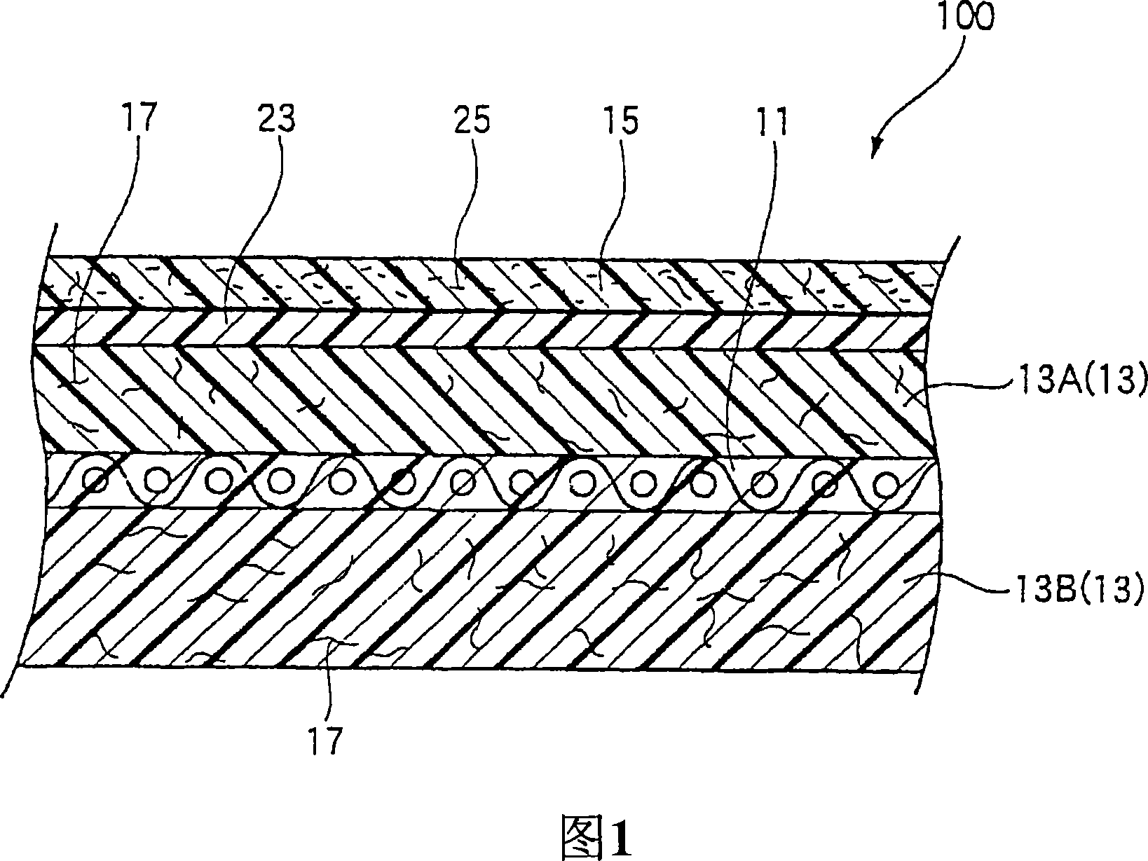
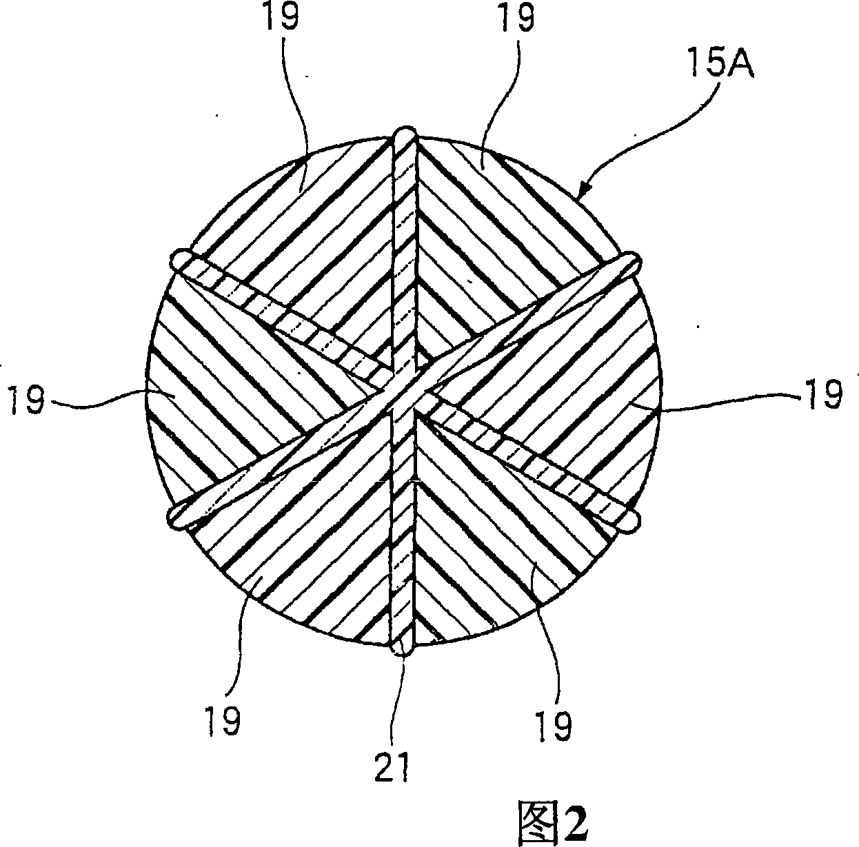
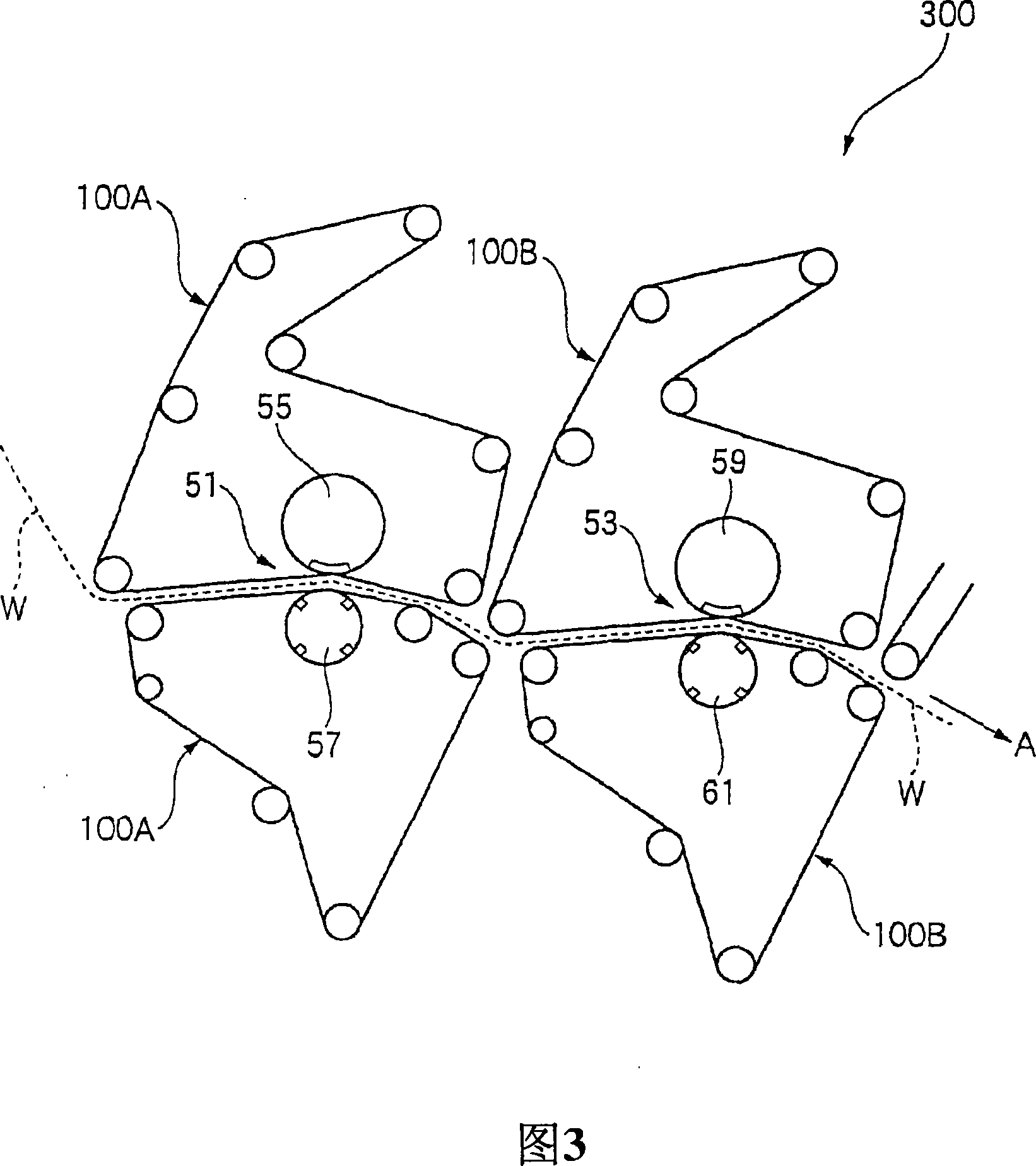
[0056] Fig. 1 is a vertical sectional view of an embodiment of a paper conveying felt 100 according to the present invention. FIG. 2 is an enlarged cross-sectional view of detached fibers used to form the wet paper contacting fibrous layer of the paper transport felt of FIG. 1. FIG. Fig. 3 is a plan view showing a schematic structure of an embodiment of a press for a paper machine according to the present invention.

[0057] As shown in FIG. 1 , the paper conveying felt 100 has a base layer 11 , a batt layer 13 (a first batt layer 13A and a second batt layer 13B), a hydrophilic nonwoven fabric layer 23 , and a wet paper contact fiber layer 15 . More specifically, the first batt layer 13A is formed on the wet paper side surface of the base layer 11, and the second batt layer 13B is formed on the press side surface of the base layer ...


PUM


Abstract

A paper transporting felt includes a base layer, a first batt layer formed on a wet paper side surface of the base layer, a second batt layer formed on a press side surface of the base layer, a wet paper contacting fibrous layer including a plurality of split fibers split into fine fibers and a high polymer elastic material impregnating gaps between the fine fibers, and formed on a wet paper side surface of the first batt layer so as to allow the fine fibers and the high polymer elastic material to come into direct contact with the wet paper, and a hydrophilic nonwoven fabric layer disposed between the first batt layer and the wet paper contacting fibrous layer. In a surface of the wet paper contacting fibrous layer which comes into direct contact with the wet paper, the fine fibers are partially covered with the high polymer elastic material.

Description

technical field [0001] The present invention relates to a paper conveying felt (felt) and a press apparatus of a paper machine having the paper conveying felt, and more particularly to a paper conveying felt for a press mechanism having a shoe press (shoe press) and A press unit of a shoe press paper machine with such a paper transport felt. Background technique [0002] Generally, a paper machine has a wire section, a press section and a dryer section. The wire mesh section, the pressing section and the drying section are arranged in this arrangement order along the wet paper conveying direction. Wet paper is conveyed and its moisture is squeezed out (that is, dehydrated) while being sequentially supplied to the paper conveying devices respectively arranged in the wire mesh part, press part and drying part, and is finally dried in the drying part. drying. The pressing device provided in the pressing section has a plurality of pressing mechanisms arranged sequentially alo...

Claims


Application Information

Patent Timeline
Patent Type & Authority Applications(China)
IPC IPC(8): D21F7/08
CPCD21F7/083
Inventor 小林靖彦大内隆司
Owner ICHIKAWA ELECTRIC CO LTD
Learn More