Power driven bending endoscope with detachable insertion portion

A technology of insertion part and detachable type, which is applied in the direction of telescope, surgery, instrument, etc., and can solve the problems of large power transmission loss and troublesome disassembly and assembly of endoscopes, etc.

Inactive Publication Date: 2007-10-17
OLYMPUS CORP
View PDF3 Cites 7 Cited by
  • Summary
  • Abstract
  • Description
  • Claims
  • Application Information

AI Technical Summary

Problems solved by technology

Therefore, the distance between the bending part and the bending control device may increase the transmission loss of the power transmitted from the bending control device to the bending part.
In addition, in general, bending drive units such as mot

Method used


Image

  • Power driven bending endoscope with detachable insertion portion
  • Power driven bending endoscope with detachable insertion portion
  • Power driven bending endoscope with detachable insertion portion

Examples


Embodiment Construction

[0029] Embodiments of the present invention will be described below with reference to the drawings.

[0030] First, a first embodiment of the present invention will be described with reference to FIGS. 1 to 5 .

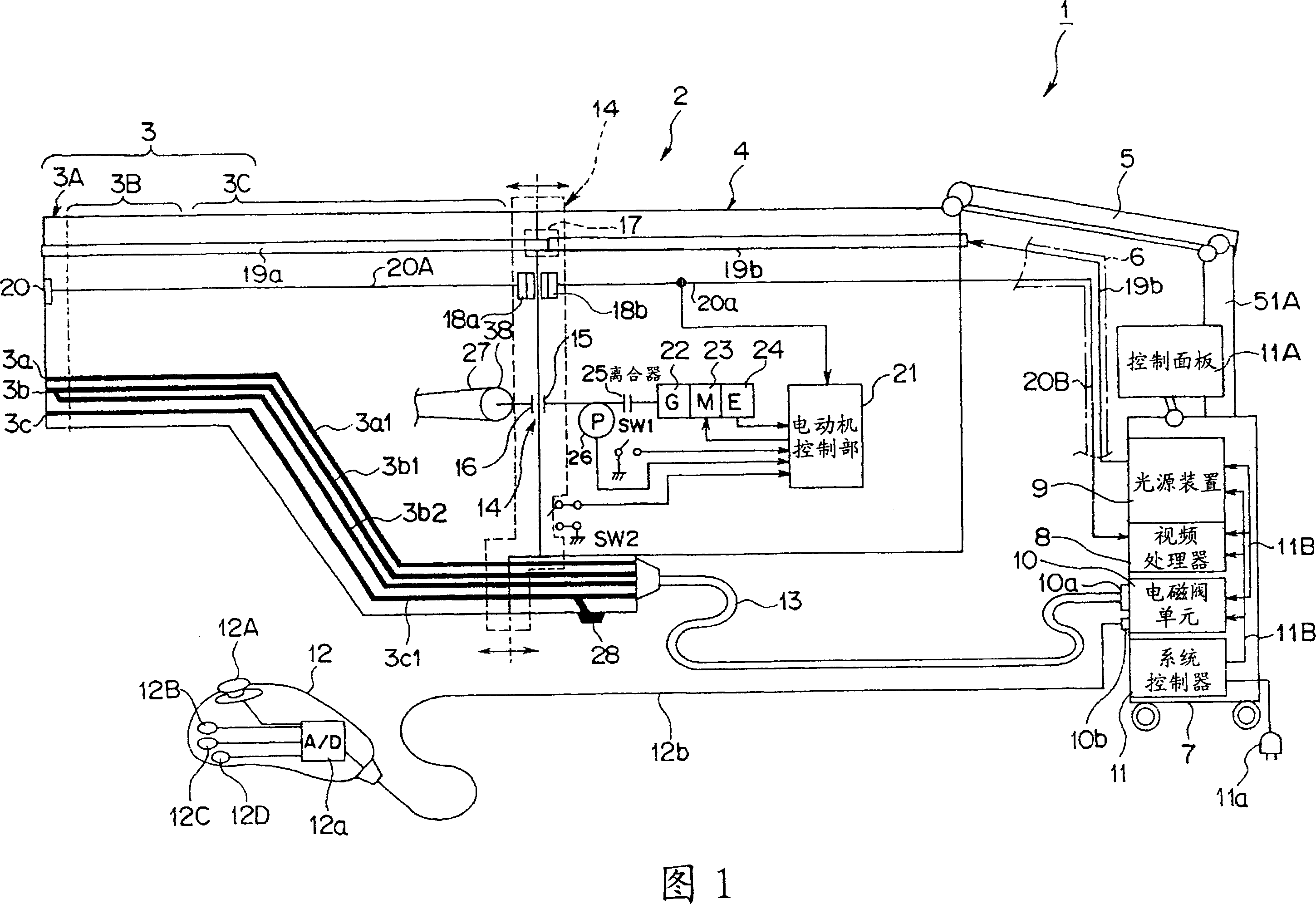
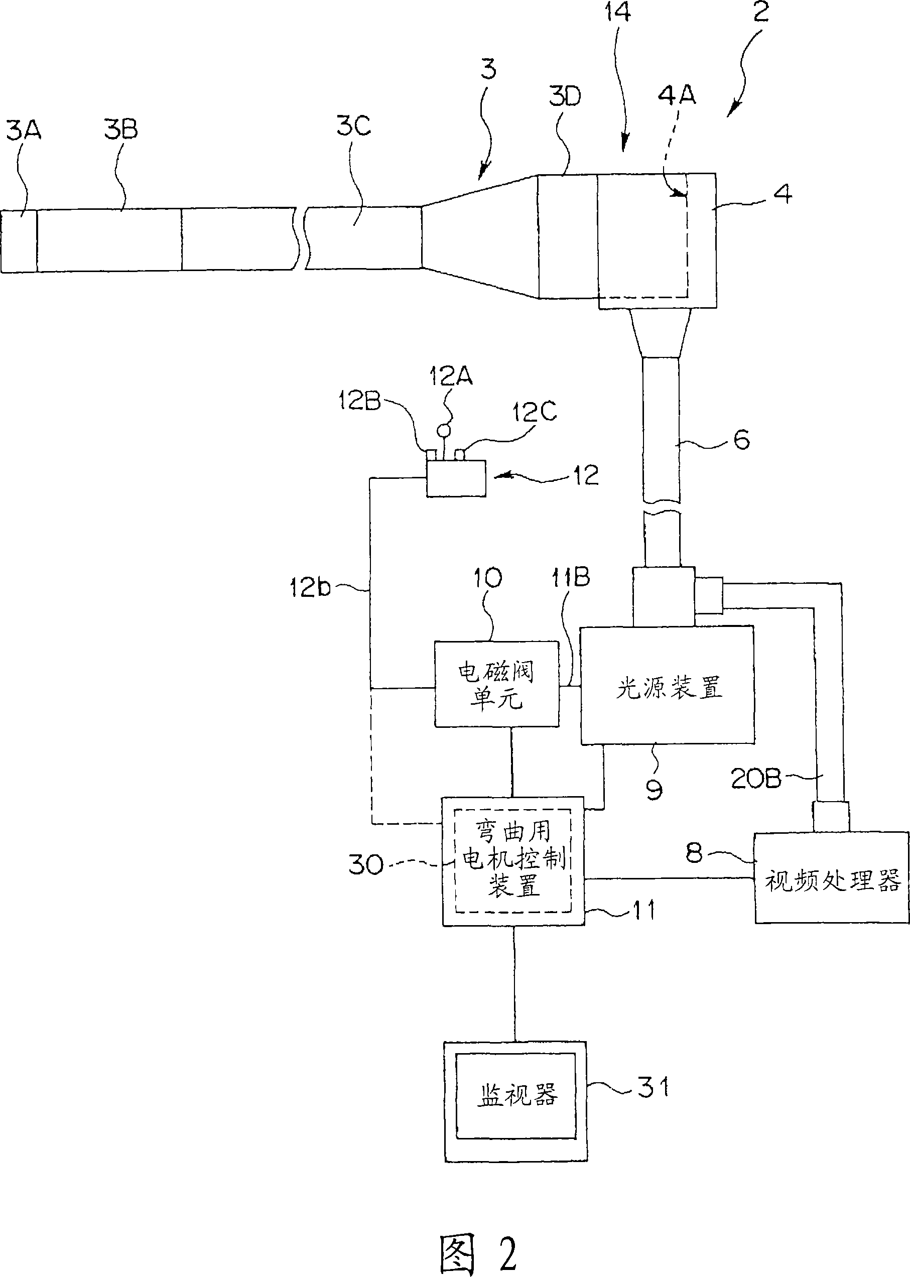
[0031] As shown in FIGS. 1 and 2 , an endoscope system 1 is composed of an insertion portion detachable electric bending endoscope (hereinafter simply referred to as an endoscope) 2 and its external devices.

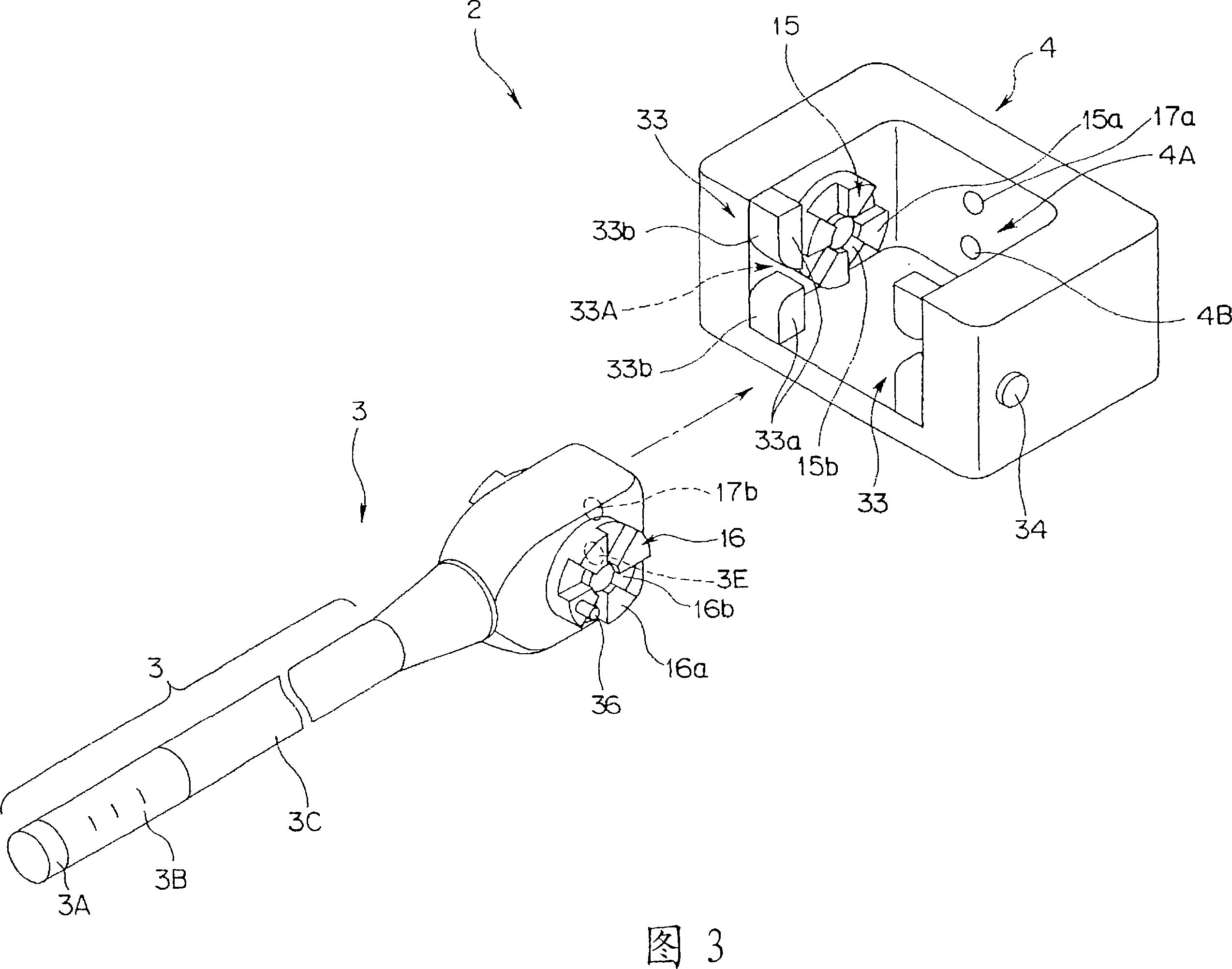
[0032] The endoscope 2 mainly includes an insertion portion main body 3 and a motor unit 4 . The motor unit 4 is a power unit. The motor unit 4 and the insertion part main body 3 are detachably configured as described later.

[0033] The insertion part main body 3 is provided with a front end rigid part 3A, a bending part 3B, a flexible tube part 3C, an insertion part engaging part 3D and the like in order from the front end side. For example, the imaging element 20 is incorporated in the distal rigid portion 3A. The bending portion 3B performs a bending ope...


PUM


Abstract

The present invention provides a power driven bending endoscope with detachable insertion portion. An electrically bendable endoscope (2) of a type where an insertion section is removable is constructed such that an insertion section body (3) and a motor unit (4) are detachable from each other, the insertion section body (3)having bendable section (3B), the motor unit (4) having an electric motor (23) for bending and driving the bendable section (3B) and a potentiometer (26) for detecting the state of bending of the bendable section (3B).

Description

technical field [0001] The present invention relates to a detachable insertion portion electric bending endoscope including an insertion portion main body having a bending portion and a bending drive unit for electrically bending the bending portion. Background technique [0002] Endoscopy has been used extensively throughout the ages. In an endoscope, by inserting an insertion portion into a body cavity, it is possible to observe the inside of the body cavity. In addition, various treatments and treatments can be performed by inserting a treatment tool into the treatment tool insertion channel provided in the insertion part as needed. [0003] Generally, in an endoscope having an elongated insertion portion, a curved portion is provided on the distal end side of the insertion portion. The bending portion is formed by connecting a plurality of bending pieces freely rotatable. The operation wire is connected to the bending piece constituting the bending portion. In additi...

Claims


Application Information

Patent Timeline
IPC IPC(8): A61B1/00G02B23/24
Inventor 上野晴彦池田裕一石塚达也古川达也正木豊小板桥正信金泽宪昭
Owner OLYMPUS CORP
Why Eureka
Try Eureka