Slipring housing with bayonet lock

a technology of slipring and bayonet lock, which is applied in the direction of current collectors, electrical devices, coupling device connections, etc., can solve the problems of large number of screws to be removed, and the disassembly is only possible with extremely high efforts, so as to reduce the cost or mass or inertia of the slipring

Active Publication Date: 2022-06-28
SCHLEIFRING GMBH
View PDF9 Cites 0 Cited by
  • Summary
  • Abstract
  • Description
  • Claims
  • Application Information

AI Technical Summary

Benefits of technology

[0010]The embodiments are providing a slipring device and a slipring housing which can easily be integrated in a complex environment and which further can easily be assembled in manufacturing and which can easily be disassembled for maintenance.
[0017]In an embodiment, the locking ring may have a bayonet lock which allows simple assembly and disassembly of the slipring device. In an alternate embodiment, the locking ring may also have a thread or any other means for holding it in position.
[0020]In another embodiment, the slipring device has a bearing arranged between the hollow shaft and the second housing. The locking ring is attached to the outside of the hollow shaft and is configured to hold the second housing against the first housing in a defined position. It may prevent the second housing from sliding off the first housing. The locking ring may be configured to hold the bearing in its position at the hollow shaft.
[0021]The housing parts when manufactured from plastic material e.g. in a 3D printing process or injection molding process might incorporate metal threaded inserts to allow stable mounting of the slipring to a customer interface or to mount a torque bridge. Also, a metal or absorbent coating might be applied to the inner housing surface for shielding of the slipring to reduce electromagnetic emissions or improve electromagnetic susceptibility of the slipring.
[0025]A simple position encoder can also be integrated by 3D printing a resistive substrate formed as a circle with the center at the rotation axis onto the inner surface of one part of the housing. The substrate is contacted by at least one electrode static to the printed substrate and a metal brush that is mounted to the other part of the housing and that moves angularly with the rotation of the slipring so that an absolute or relative resistor value measured between the sliding brush and the at least one static electrode represents an angular position between the two housings to serve as an encoder. The housing might also only partially cover the slipring to reduce costs or mass or inertia of the slipring. Connectors might be mounted to the housing or to at least one of the printed circuit boards.

Problems solved by technology

It has a very high degree of sealing, but requires a large number of screws to be removed for opening the housing.
Due to the complex interior assembly and the multiply screwed housing, the disassembly is only possible with extremely high efforts.
This is a significant advantage over standard manufacturing methods, as these do not allow to combine the spring with the locking ring.

Method used


Image

  • Slipring housing with bayonet lock
  • Slipring housing with bayonet lock
  • Slipring housing with bayonet lock

Examples


first embodiment

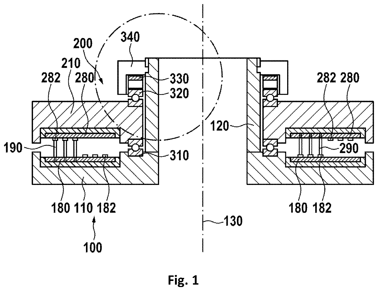
[0040]In FIG. 1, a slipring device is shown. The slipring device basically includes a first part 100 and a second part 200, which are rotatable against each other about a center axis 130. The first part 100 has a first housing 110 which holds a first printed circuit board (PCB) 180. This PCB may hold at least one first sliding track 182 and / or at least one contact brush 190.

[0041]The second part 200 has a second housing 210 with a second PCB 280. The second PCB 280 may have at least one second contact brush 290 and at least one second sliding track 282. The sliding tracks and brushes are arranged such that a sliding track of the first PCB interfaces with a sliding brush of the second PCB, and vice versa to accomplish an electrical contact. Between the first housing 110 and the second housing 210 is at least a first bearing 310 which provides mechanical support and allows rotation of the second housing against the first housing. There may be at least a second bearing 320. The first h...

second embodiment

[0047]In FIG. 6, a slipring device is shown. The slipring device is similar to the slipring device of FIG. 1, but has different bearings. Here, instead of ball bearings, slide bearings, also called friction bearings are used. Such bearings have surfaces sliding against each other. In this embodiment, the ball bearings are replaced by a first slide bearing 410 and a second slide bearing 420.

[0048]FIG. 7 shows a detail of the locking ring with bayonet lock and a slide bearing. This is a detail of the previous figure.

third embodiment

[0049]FIG. 8 shows a slipring device. Here, no discrete slide bearings are used as in the previous embodiment. Instead, the second housing 210 may be sliding within first housing 110 and hollow shaft 120. The first housing 110 and the hollow shaft 120 may also be one part. There may be a bearing gap 510 between the second housing 210 slidably against first housing 110 and hollow shaft 120. There may be a lubricant in the bearing gap.

[0050]FIG. 9 shows a detail of the locking ring of the previous embodiment. There may be a counter bearing 520 to hold the second housing 210 in place. This counter bearing may also be part of the locking ring.

[0051]In FIG. 10, a further embodiment of a slipring device is shown. The slipring device is similar to the slipring device of FIG. 1, but has only one bearing, which may be a ball bearing.

[0052]FIG. 11 shows a detail of the locking ring of the previous embodiment.


PUM


Abstract

A slipring device includes a first part and a second part rotatable against each other. Both parts include housings with slipring components. A first housing at the first part has a hollow shaft with a bayonet lock notch to engage with a locking ring having at least one bayonet lock protrusion. The locking ring can easily be attached by a bayonet lock to lock the first part and the second part together.

Description

CROSS-REFERENCE TO RELATED APPLICATIONS[0001]This application is a continuation of pending International Application No. PCT / EP2020 / 061044 filed on 21 Apr. 2020, which designates the United States and claims priority from European Application No. 19180216.4 filed on 14 Jun. 2019, both of which are incorporated herein by reference.BACKGROUND1. Field of the Invention[0002]The invention relates to slipring devices for transmission of electrical signals between rotating parts. Specifically, it relates to housings of such slipring devices.2. Description of Related Art[0003]Electrical sliprings are used to transfer electrical power and / or signals between a rotating and a stationary part. Such sliprings are used in different applications, like wind energy plants or computer tomography scanners. There exist also many industrial, military, and aerospace applications in which sliprings are used.[0004]Specifically for industrial applications, the sliprings should have a housing which allows si...

Claims


Application Information

Patent Timeline
Patent Type & Authority Patents(United States)
IPC IPC(8): H01R13/625H01R13/66H01R39/64H01R39/14H01R39/10
CPCH01R13/625H01R13/6658H01R39/10H01R39/14H01R39/643
Inventor RECKNAGEL, JENS
Owner SCHLEIFRING GMBH
Why Eureka
Try Eureka