Screw for vascular occlusion

A technology of screws and blood vessels, applied in the field of implantable devices, which can solve the problem of not interfering with the entry/approach of the surgical field

Inactive Publication Date: 2007-10-17
罗尔夫·因德比茨
View PDF2 Cites 1 Cited by
  • Summary
  • Abstract
  • Description
  • Claims
  • Application Information

AI Technical Summary

Problems solved by technology

Furthermore, such devices should not interfere with access / access to the surgical field

Method used


Image

  • Screw for vascular occlusion
  • Screw for vascular occlusion
  • Screw for vascular occlusion

Examples


Embodiment Construction

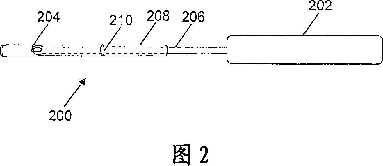
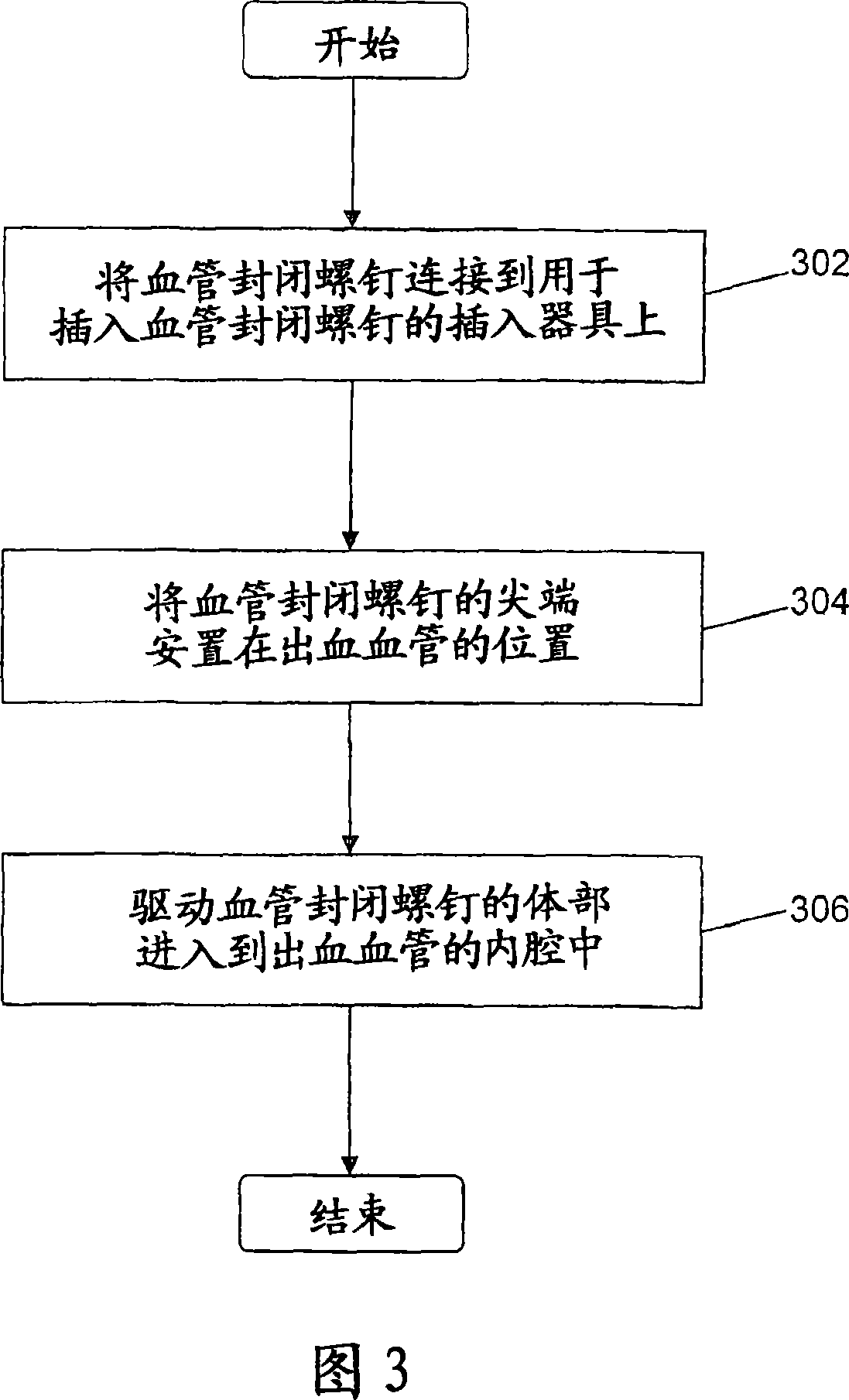
[0030] The present invention discloses a vessel sealing screw system (VOSS) for sealing blood vessels during surgical procedures. In particular, the present invention provides vessel sealing screws for sealing off bleeding spinal and lumbar arteries during surgical procedures to repair abdominal aortic aneurysms. The vessel sealing screw has a threaded body that helps securely seal off the lumen of the vessel. The present invention also provides an insertion tool for inserting a blood vessel sealing screw into the lumen of a blood vessel.

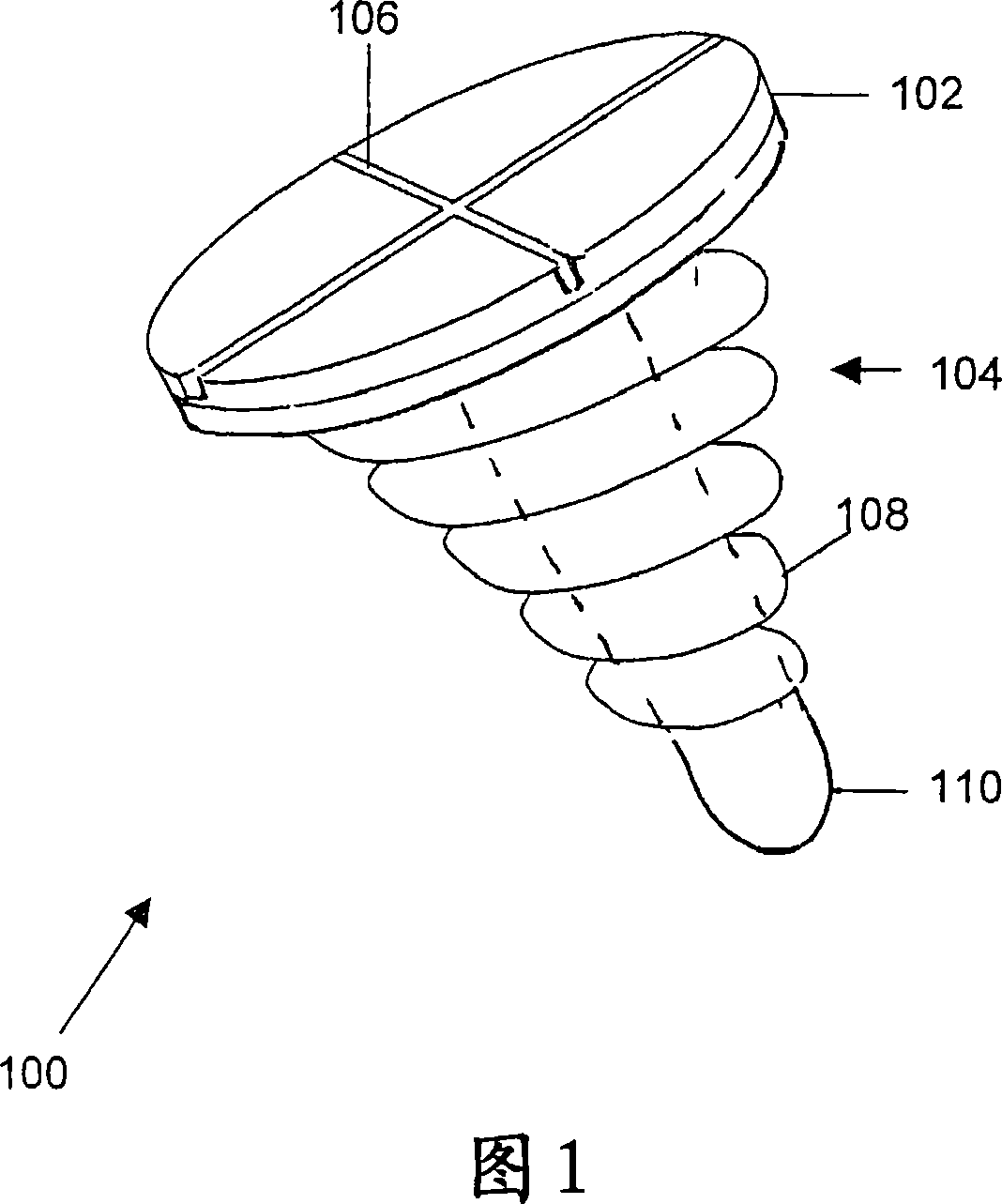
[0031] FIG. 1 is an illustration of a vessel sealing screw 100 in accordance with an embodiment of the present invention. The vessel sealing screw 100 has a screw head 102 and a body 104 . Force acts on the screw head 102 to secure the vessel closure screw 100 into the lumen of the vessel. The screw head 102 has a groove 106 on one surface. According to an embodiment of the present invention, groove 106 is a cross groove. The body 104 ...


PUM


Abstract

The present invention provides a vascular occlusion screw (100) for essentially blood-tight occlusion of a blood vessel, the vascular occlusion screw comprising: a. a basically rigid screw head (102) for fixing the vascular occlusion screwinside the lumen of the blood vessel, the screw head comprising at least one groove (106) for attachment with an insertion instrument; and b. a semi-rigid or elastic body (104), the body having a threaded surface helping to occlude the lumen of the blood vessel.

Description

technical field [0001] The invention relates to the field of medical instruments. In particular, the present invention relates to an implantable device for sealing (occluding) a blood vessel during a surgical procedure. Background technique [0002] Blood vessels need to be sealed during surgical procedures to control blood loss. An example of such a surgical procedure is the surgical treatment of an abdominal aortic aneurysm. [0003] An abdominal aortic aneurysm is a dilation of the abdominal aorta due to weakening of the abdominal aortic wall. An abdominal aortic aneurysm can cause complications, such as a natural rupture of the wall of the abdominal aorta. The risk of spontaneous rupture increases when the transverse dimension of the aneurysm exceeds 5 cm. [0004] The natural rupture of an abdominal aortic aneurysm results in massive internal bleeding that has proven fatal within minutes. Other problems that an abdominal aortic aneurysm can cause include embolism i...

Claims


Application Information

Patent Timeline
Patent Type & Authority Applications(China)
IPC IPC(8): A61B17/12
CPCA61B17/12159A61B17/12022
Inventor 罗尔夫·因德比茨
Owner 罗尔夫·因德比茨
Why Eureka
Try Eureka