
Compact incandescent lamp with integrated reflector

A technology that integrates reflectors and incandescent lamps, and is used in incandescent lamps, incandescent lamp parts, reflectors, etc.

Inactive Publication Date: 2007-10-17
KONINKLIJKE PHILIPS ELECTRONICS NV
View PDF1 Cites 1 Cited by
  • Summary
  • Abstract
  • Description
  • Claims
  • Application Information

AI Technical Summary

Problems solved by technology

These additional optics come with additional expense and often additional space requirements

Method used


Image

  • Compact incandescent lamp with integrated reflector
  • Compact incandescent lamp with integrated reflector

Examples


Embodiment Construction

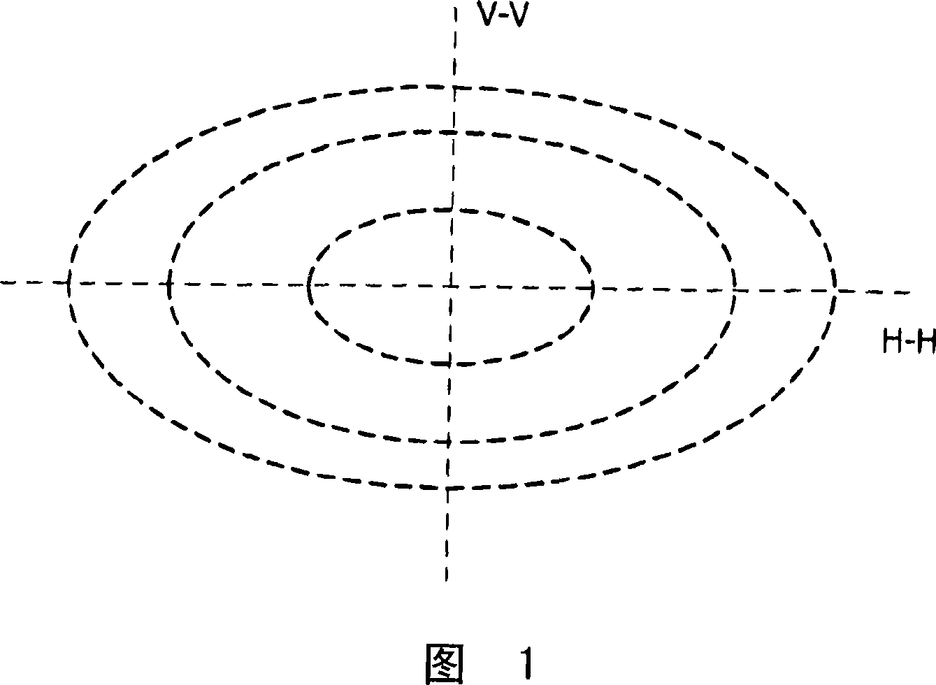
[0032] Figure 1 shows a schematic diagram of non-axisymmetric illumination.

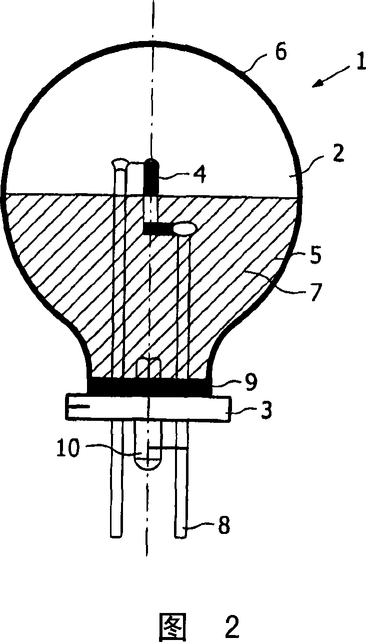
[0033] FIG. 2 shows an incandescent lamp 1 according to the invention in a schematic side view. The non-axisymmetric bulb 2 is tightly connected to the bulb 2 by means of an enamel 9 , in particular using a molded glass pane 3 . In addition, an incandescent element 4 is fastened to this glass pane 3 . The positioning of the glass pane 3 relative to the incandescent element 4 has a technical manufacturing tolerance of approximately + / −0.25 mm in the axial direction and approximately + / −0.2 mm in the transverse direction. The incandescent element 4 is connected to a contact 8 which is sealed through the glass plate 3 . The metal tube 10 is likewise sealed through the glass plate 3 .

[0034] In a lamp of this type, the incandescent element 4 is arranged in a defined manner within the bulb 2 and is thus also positioned in a defined manner relative to the reflector layer 5 .

[0035] A reflective lay...


PUM


Abstract

The invention relates to a compact incandescent lamp with an integrated reflector, comprising at least a lamp bulb, on one part of the surface of which the reflector is applied as a reflective layer and another part thereof is a light output window, an incandescent element, which is arranged in a defined way in the lamp bulb and is positioned in a defined way with respect to the reflective layer, wherein at least the part of the lamp bulb which carries the reflective layer is non-axisymmetric and / or a part of the light output window is asymmetrically shaped, so that the visible light which the lamp can generate illuminates a region of space non-axisymmetrically.

Description

technical field [0001] The invention relates to a compact incandescent lamp with an integrated reflector, comprising at least a bulb, on one part of its surface coated with the reflector as a reflective layer and the other part as a light output window, and an incandescent element, arranged in a prescribed manner It is positioned in a defined manner within the bulb and relative to the reflective layer. [0002] In addition to the above two regions, there may be at least one other region on the bulb. Background technique [0003] Lamps of the above-mentioned type, which due to their function require an axisymmetrically shaped bulb, have been known for many years. This is in particular due to the efficient way in which such axisymmetrically shaped bulbs can be produced within the scope of industrial mass production. [0004] For many applications, a lamp with such a bulb produces light which is able to illuminate a spatial region particularly uniformly but always on average ...

Claims


Application Information

Patent Timeline
IPC IPC(8): H01K1/32H01J61/40H01K1/26F21V7/00H01J61/04F21V9/08H01J61/35F21V13/08F21Y101/00
CPCH01K1/325H01K7/02H01K1/28H01K1/26H01K1/32
Inventor W·施拉格L·黑南B·斯平格J·E·德弗里斯
Owner KONINKLIJKE PHILIPS ELECTRONICS NV
Learn More