Cylinder deflaker

A technology of decompression machine and cylinder, which is applied in the field of papermaking machinery, can solve the problems that the waste paper mass cannot be completely decompressed, the efficiency is low, the waste of raw materials, etc., and achieves the effect of simple structure, enhanced decompression ability, and improved decompression efficiency.

Inactive Publication Date: 2012-02-08
VALMET TECH OY
View PDF0 Cites 0 Cited by
  • Summary
  • Abstract
  • Description
  • Claims
  • Application Information

AI Technical Summary

Problems solved by technology

[0003] In use, it was found that the cylinder deflaker only uses the shear force generated by the falling of the pulp to decompose the waste paper, and the efficiency is low, and sometimes the large waste paper group cannot be completely deflagrated, so it is discharged as waste residue, causing waste of raw materials

Method used


Image

  • Cylinder deflaker
  • Cylinder deflaker
  • Cylinder deflaker

Examples


Embodiment 1

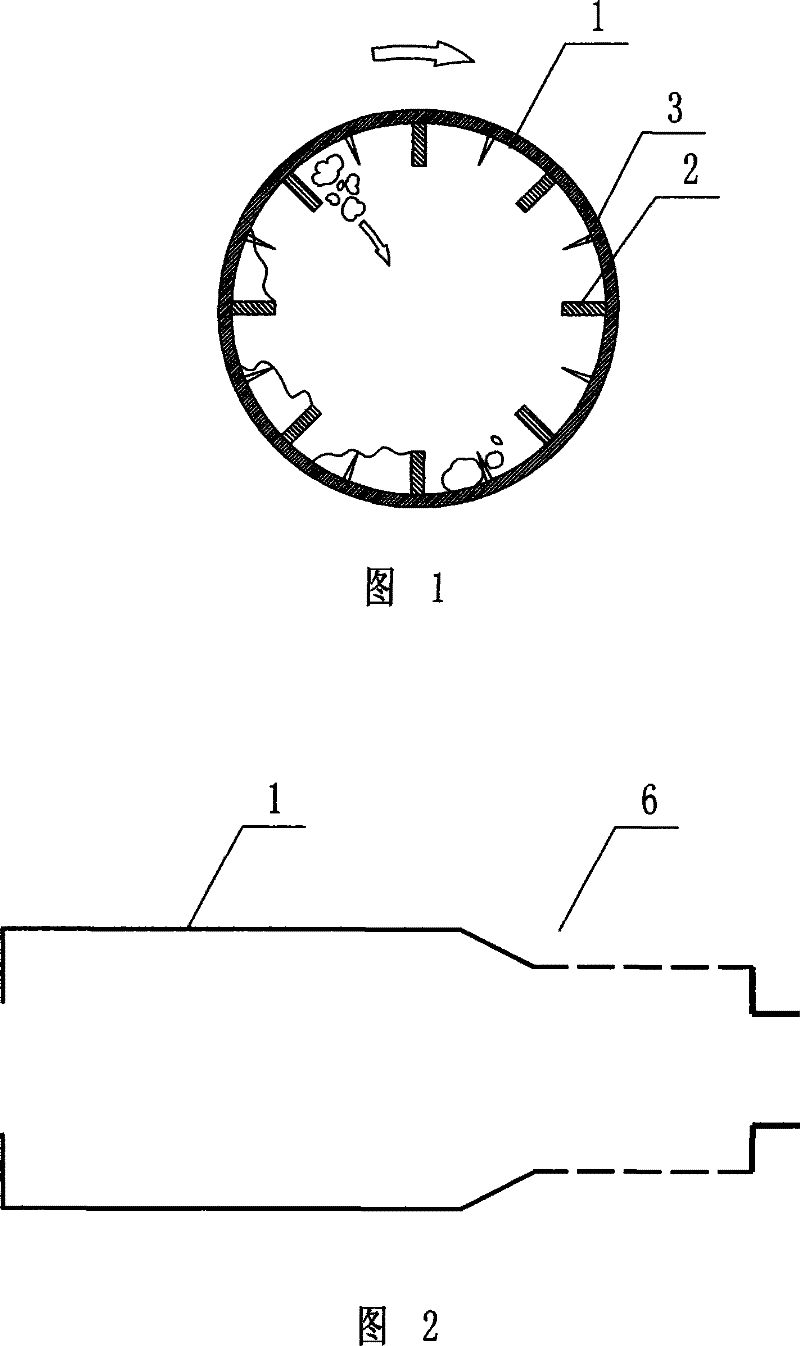
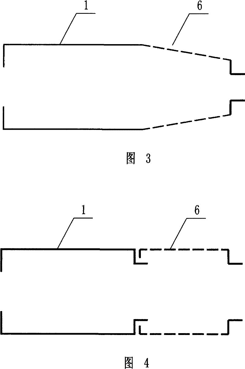
[0020] Embodiment one: if figure 1 , figure 2 As shown, the cylinder flaking machine includes a flaking machine cylinder, and the flaking machine cylinder is divided into a pulping area cylinder 1 and a screening area cylinder 6, and the inner wall of the pulping area cylinder 1 is provided with a partition 2. Between the two adjacent partitions 2, there are a number of disintegrating teeth 3 whose tips point to the center of the cylinder in the pulping zone. The cylinder 1 in the pulping zone and the cylinder 6 in the screening zone are an integrated structure in the prior art structure, and the cylinder body of the cylinder screen close to the cylinder 1 in the pulping zone is a conical structure. The cylindrical sieve can also be used as attached image 3 conical configuration as shown, or use the attached Figure 4 In the split structure shown, the cylinder 1 in the pulping area and the cylinder 6 in the screening area are separated, and the cylinder 6 in the screenin...

Embodiment 2

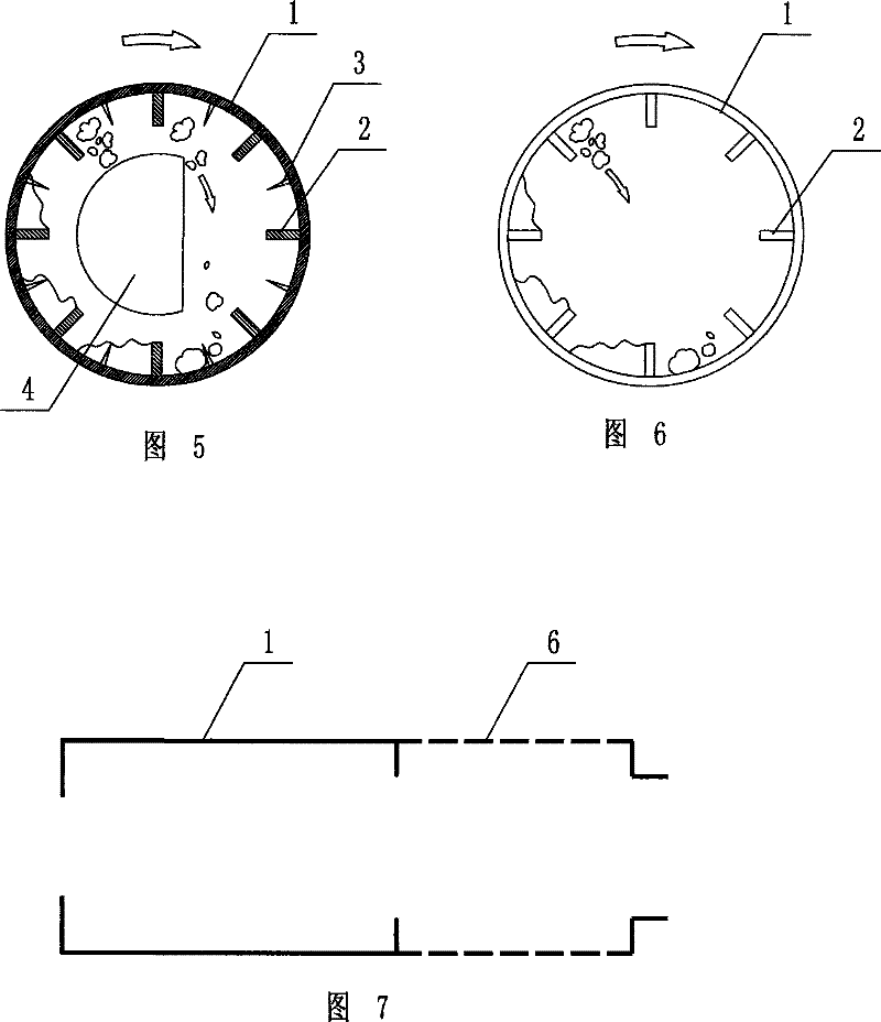
[0023] Embodiment two: if Figure 5 As shown, this embodiment is basically the same as Embodiment 1, except that a "D"-shaped drum core 4 is arranged in the cavity of the pulping zone cylinder 1 along the axial direction of the cylinder pulping zone, so that The circular surface of the "D" shaped drum core 4 is located in the ascending area of ​​the waste paper ball.

[0024] Under the action of the "D" shaped drum core 4 and the partition, the waste paper ball is picked up by the partition and moved to the top of the cylinder. During this process, the debonding teeth and the "D" shaped drum core 4 move relatively Tear the moving paper balls to each other and decompose the waste paper balls; when the waste paper balls turn over the top of the drum, relying on gravity and inertia, the waste paper balls fall down from the vertical side of the "D" shaped drum core 4, and when they fall to the bottom At the end, the debonding teeth at the bottom decompose the waste paper again, s...


PUM


Abstract

The present invention discloses a cylindrical fluffer including fluffer cylinder. Said fluffer cylinder is divided into pulp shredding zone cylinder and screening zone cylinder, the inner wall of said pulp shredding zone cylinder is equipped with baffle boards, several fluffer gears which tip parts towards the centre of pulp shredding zone cylinder are installed between said adjacent two baffle boards; waste paper agglomerates are held by the baffle board and moved under cylinder, the waste paper agglomerates falls down leaning on gravity and inertia, the fluffer gears tears the waste paper agglomerates at the moment and the waste paper agglomerates is unfolded and falls down; further the waste paper agglomerates are broken up by the fluffer gears on bottoms when the papers falls down at bottom; the invention enhances the relief capacity of the cylindrical fluffer and has simple structure, the relief efficiency is increased more than 30%.

Description

technical field [0001] The invention relates to a papermaking machine, in particular to a cylinder fluffing machine. Background technique [0002] The advantage of the cylinder deflaker is that it decomposes waste paper fibers without chopping waste and producing fine fibers, without consuming unnecessary stirring, cutting fibers and impurities, and low energy consumption; if attached Figure 6 , attached Figure 7 As shown, the cylinder includes a pulping area and a screening area. The working principle of the pulping area is that the waste paper entering the pulping area is soaked by water and chemicals. Since the cylinder is slightly inclined, the waste paper is slowly discharged by gravity. Moving forward, the partition on the inner wall of the cylinder continuously picks up the waste paper and drops it to the bottom of the cylinder at a certain height, and uses the shearing force to loosen the fibers of the waste paper without breaking the waste. [0003] In use, it wa...

Claims


Application Information

Patent Timeline
Patent Type & Authority Patents(China)
IPC IPC(8): D21B1/32
CPCY02W30/64
Inventor 李风宁
Owner VALMET TECH OY
Why Eureka
Try Eureka