Slit gauge

A technology of slit gauges and mobile brackets, applied in the field of slit gauges, can solve the problems of cumbersome replacement, reduce production auxiliary time, and reduce costs, and achieve the effects of ensuring stability, reducing production auxiliary time, and reducing costs

Active Publication Date: 2007-10-24
CRRC QISHUYAN INSTITUTE CO LTD
View PDF0 Cites 4 Cited by
  • Summary
  • Abstract
  • Description
  • Claims
  • Application Information

AI Technical Summary

Problems solved by technology

[0003] The purpose of this invention is to design a slit gauge to solve the problem of tedious replacement, reduce production auxiliary time, and make a device universal, thereby reducing costs

Method used


Image

  • Slit gauge
  • Slit gauge
  • Slit gauge

Examples


Embodiment Construction

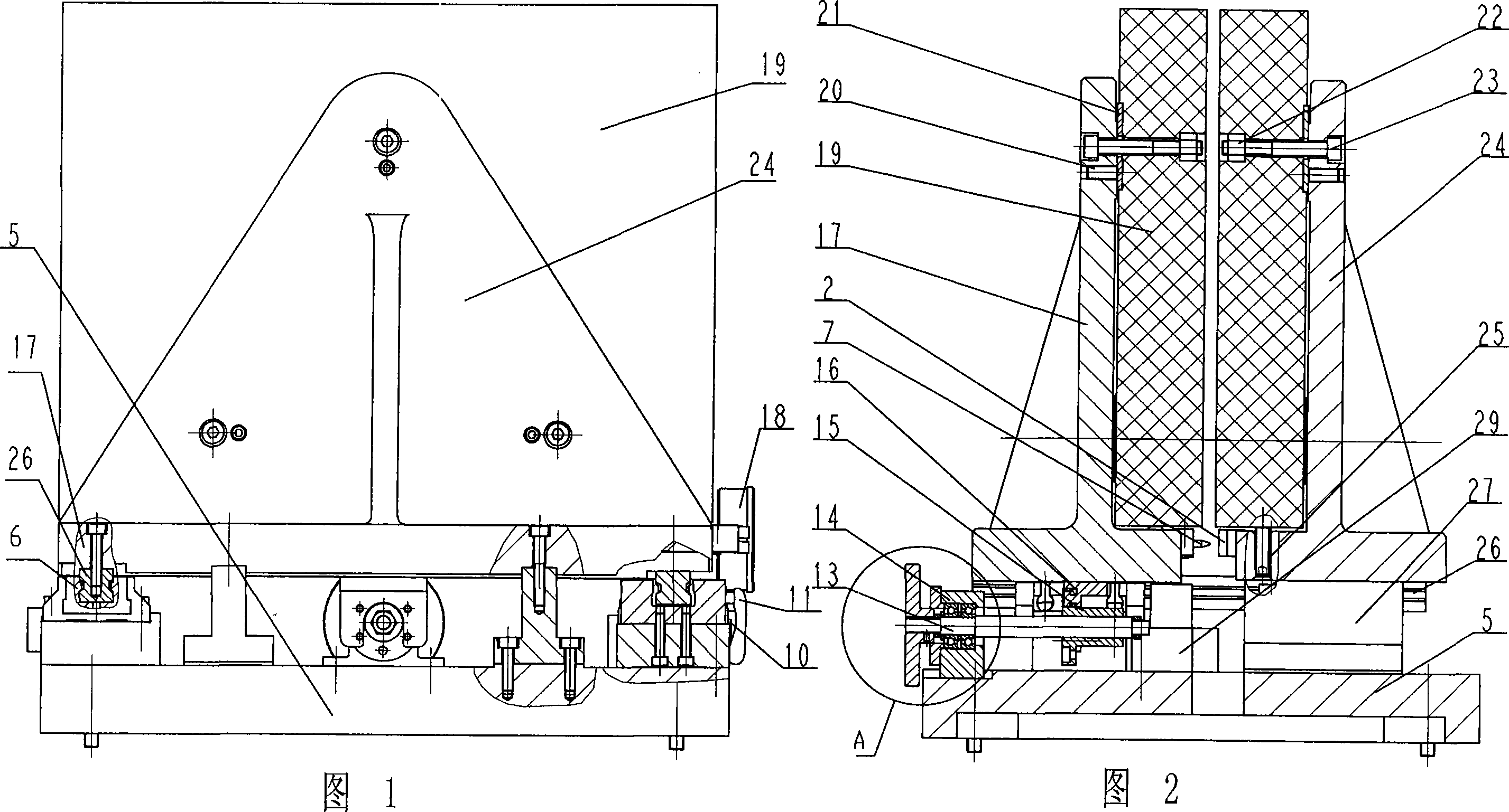
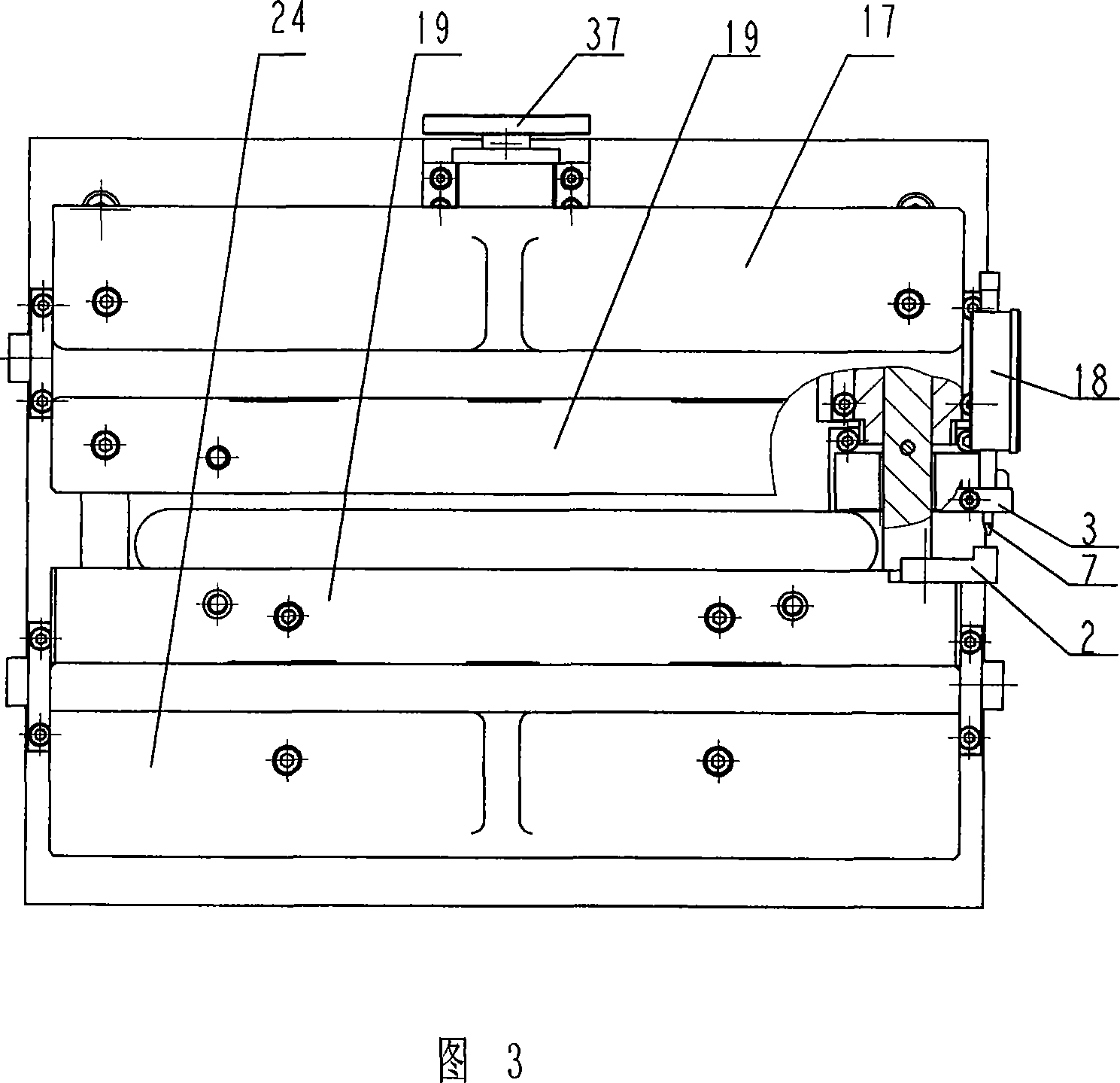
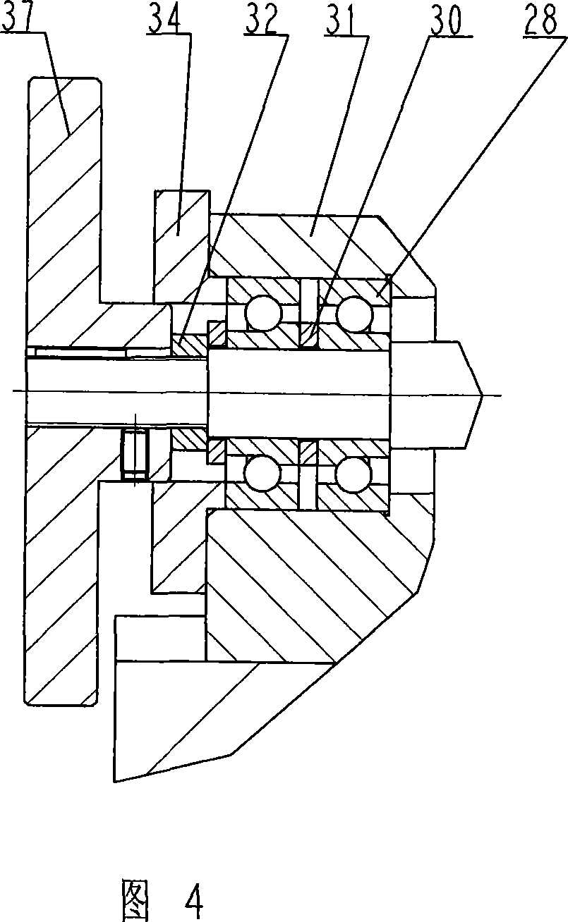
[0016] In the figure: 1. Left locking block; 2. Reference block; 3. Guide frame; 4. Right locking block; 5. Base; 6. Guide rail; 7. Thimble; 10. Press block; 11. Handle; 12. Screw; 13, screw; 15, nut; 16, transmission bracket; 17, mobile bracket; 18, dial indicator; 19, detection plate; 20, positioning pin; 21, gasket; 22, nut; 23, bolt ; 24, fixed bracket; 25, screw; 26, slider; 27, the support of the fixed bracket, used to install the fixed bracket on the base; 28, the bearing; 29, the locking block support, used to connect and lock Block and base; 30, washer; 31, bearing seat; 32, nut; 34, bearing cover; 37, handwheel.

[0017] As shown in the figure: a fixed bracket 24 is installed on one side of the base 5, and a mobile bracket 17 is installed on the other side. The fixed bracket 24 and the mobile bracket 17 are parallel to each other, and two detection plates 19 are respectively installed on the fixed bracket 24 and the mobile bracket 17. The inner side; the mobile brac...


PUM


Abstract

The invention belongs to a piston ring flexibility detecting device, in particular to a slit ruler. The inventive slit ruler comprises two detecting plates which can move relatively. The invention is characterized in that one side of a base is mounted with a fixed support, while another side is mounted with a movable support, the fixed support and the movable support are parallel, the two detecting plates are respectively mounted at the inner side of the fixed support and the movable support, the movable support is sliding connected on the base, and a pushing device for pushing the movable support is arranged between the movable support and the base. The invention can effectively resolve problem as frequent exchange, reduce producing time, make device with general service and reduce cost.

Description

technical field [0001] The invention belongs to a detection device for the deflection of a piston ring, in particular to a slit gauge. Background technique [0002] The inspection of the deflection of the piston ring is a necessary inspection item for finished product acceptance. The current detection device is two fixed detection plates, and the distance between the four plates in the middle is determined by the contour pads, and the four contour pads are sandwiched between the two detection plates. , The distance between the detection plates is determined by these contour gaskets. When testing different piston rings, different contour gaskets or multiple detection devices must be replaced. Contents of the invention [0003] The purpose of the present invention is to design a slit gauge to solve the problem of cumbersome replacement, reduce production auxiliary time, and make a device universal, thereby reducing costs. [0004] According to the technical solution provide...

Claims


Application Information

Patent Timeline
IPC IPC(8): G01B3/30
Inventor 赵文鑫周忠
Owner CRRC QISHUYAN INSTITUTE CO LTD
Why Eureka
Try Eureka