Electric binding terminal

A technology of connecting terminals and connecting terminals, applied in the direction of electrical components, connecting end caps, conductive connections, etc., can solve problems such as limiting the minimum cross-section of current conduction

Active Publication Date: 2007-10-24
维哥经营公司MBH
View PDF4 Cites 17 Cited by
  • Summary
  • Abstract
  • Description
  • Claims
  • Application Information

AI Technical Summary

Problems solved by technology

As far as the precious copper material is concerned, such strip or rod-shaped busbars already limit the minimum cross-section for current conduction

Method used


Image

  • Electric binding terminal
  • Electric binding terminal

Examples


Embodiment Construction

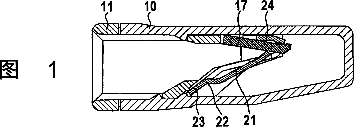
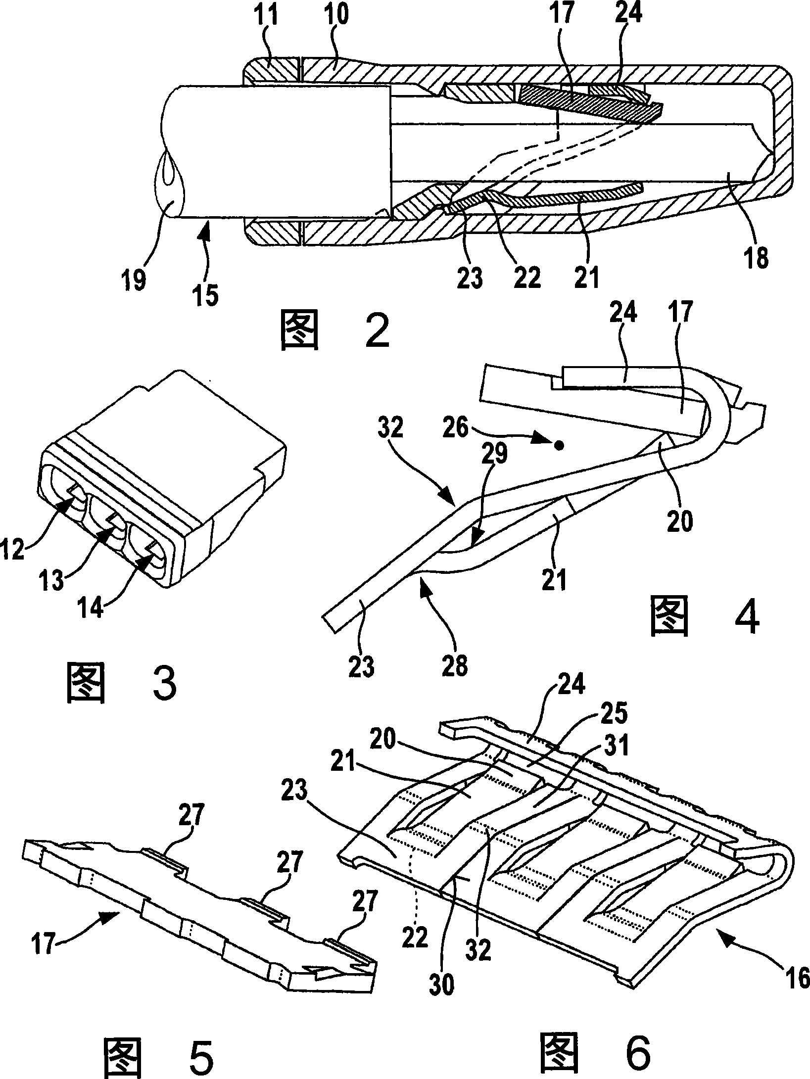
[0023] Fig. 1 shows the cross-sectional view of terminal box 10, and terminal box 10 has a box cover 11 that is arranged along the wire insertion direction, and this box cover 11 has wire insertion openings 12, 13 and 14, so that the total number of inserting in the same orientation and parallel is Three wires 15 (see Figure 3).

[0024] Figures 4, 5 and 6 show the contacts incorporated into the terminal box. The contact is composed of a spring steel plate 16 (see FIG. 6 ) and a bus bar 17 (see FIG. 5 ), and the bus bar 17 is made of copper with good electrical conductivity.

[0025] Corresponding to the number of clamping points, three leaf spring tongues 21 are punched out of the spring steel plate 16 , whereby window recesses are produced in the spring steel plate. The size of the window recess corresponds substantially to the size of the punched-out leaf spring plus the end section 25 , best seen in FIG. 6 . The wires 15 are inserted through the window openings, and the ...


PUM


Abstract

The present invention relates to a connection terminal for electric wires. The terminal works with leaf spring tongues punched (or stamped) out of a spring steel plate and has a bus bar extending over all clamping points. The object of the invention is to reduce the overall height of the terminals. This task is solved by the new positioning of the edge regions of the spring steel sheets so that each one adjoins the wires closely. A reduction in the overall height can also be achieved by a new contact construction with a special pre-deformation of the leaf spring tongues.

Description

technical field [0001] The invention relates to an electrical terminal for the connection of electric wires to terminal boxes made of insulating material and for the connection of electric wires to a contact (Kontakteinsatz) having a plurality of adjacently arranged in a row Clamping locations, the stripped ends of the wires are inserted parallel to each other from the same side of the terminal box into adjacently arranged clamping locations. Background technique [0002] The contacts of such terminals usually consist of a spring steel plate and a bus bar made of a material with good electrical conductivity and common to all clamping points. Corresponding to the number of clamping points, a plurality of leaf springs in the form of leaf spring tongues are punched out of the spring sheet metal block, whereby their tongue bases are connected to the upper edge region of the spring sheet metal. The free ends of the leaf spring tongues extend in the direction of the lower edge of...

Claims


Application Information

Patent Timeline
Patent Type & Authority Applications(China)
IPC IPC(8): H01R4/48
CPCH01R4/4818H01R4/22H01R9/24H01R11/09H01R2101/00H01R4/48185H01R4/48
Inventor H-J·考勒曼
Owner 维哥经营公司MBH
Why Eureka
Try Eureka