
Chair

A technology for chairs and supporting components, which is applied to chairs, chairs with vertically adjustable seats, and other seating furniture, etc., which can solve problems such as cumbersome component connection structures, users’ weight not being stably supported, and component damage

Inactive Publication Date: 2007-10-24
李秉哲
View PDF0 Cites 1 Cited by
  • Summary
  • Abstract
  • Description
  • Claims
  • Application Information

AI Technical Summary

Problems solved by technology

Thus, the user's weight is not stably supported, and moments act on the corresponding joints, thus causing damage to the components
[0007] Further, the problem of the conventional chair is that the joint structure of the parts is quite cumbersome and complicated, thus resulting in high product cost

Method used


Image

  • Chair
  • Chair
  • Chair

Examples


Embodiment Construction

[0040] Hereinafter, the present invention will be described in detail with reference to the accompanying drawings.

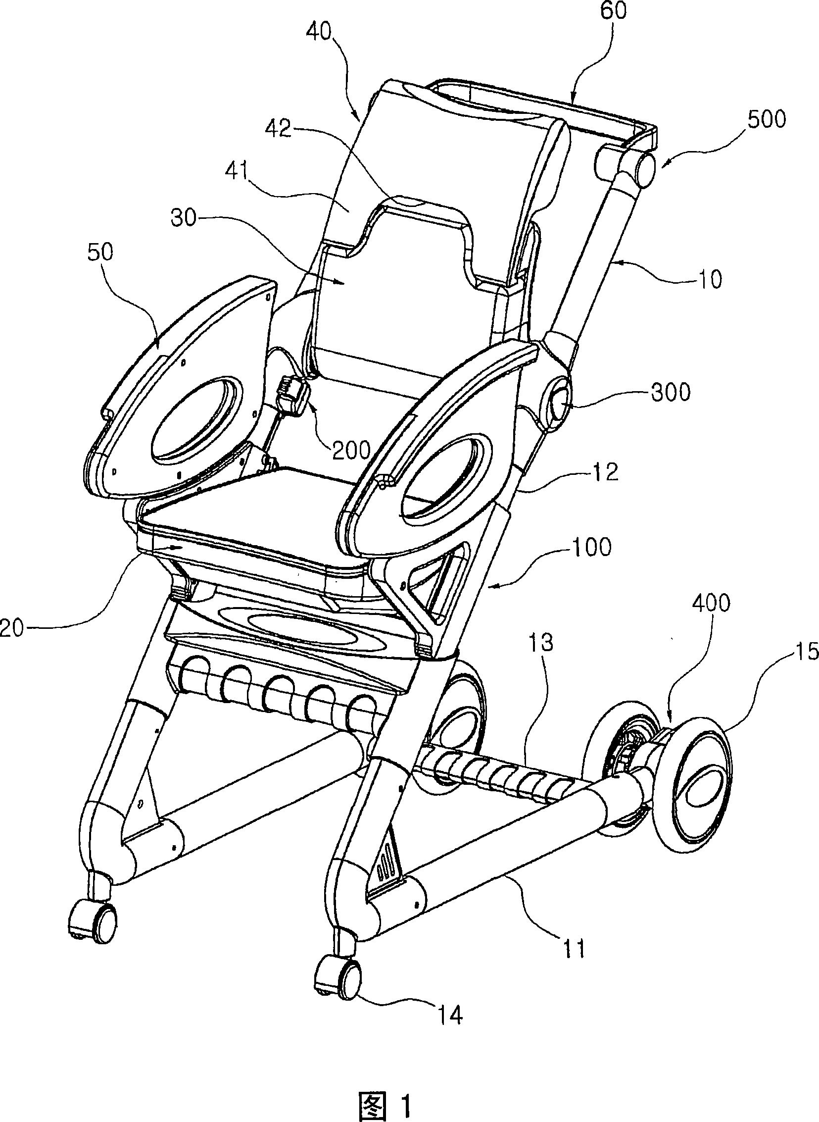
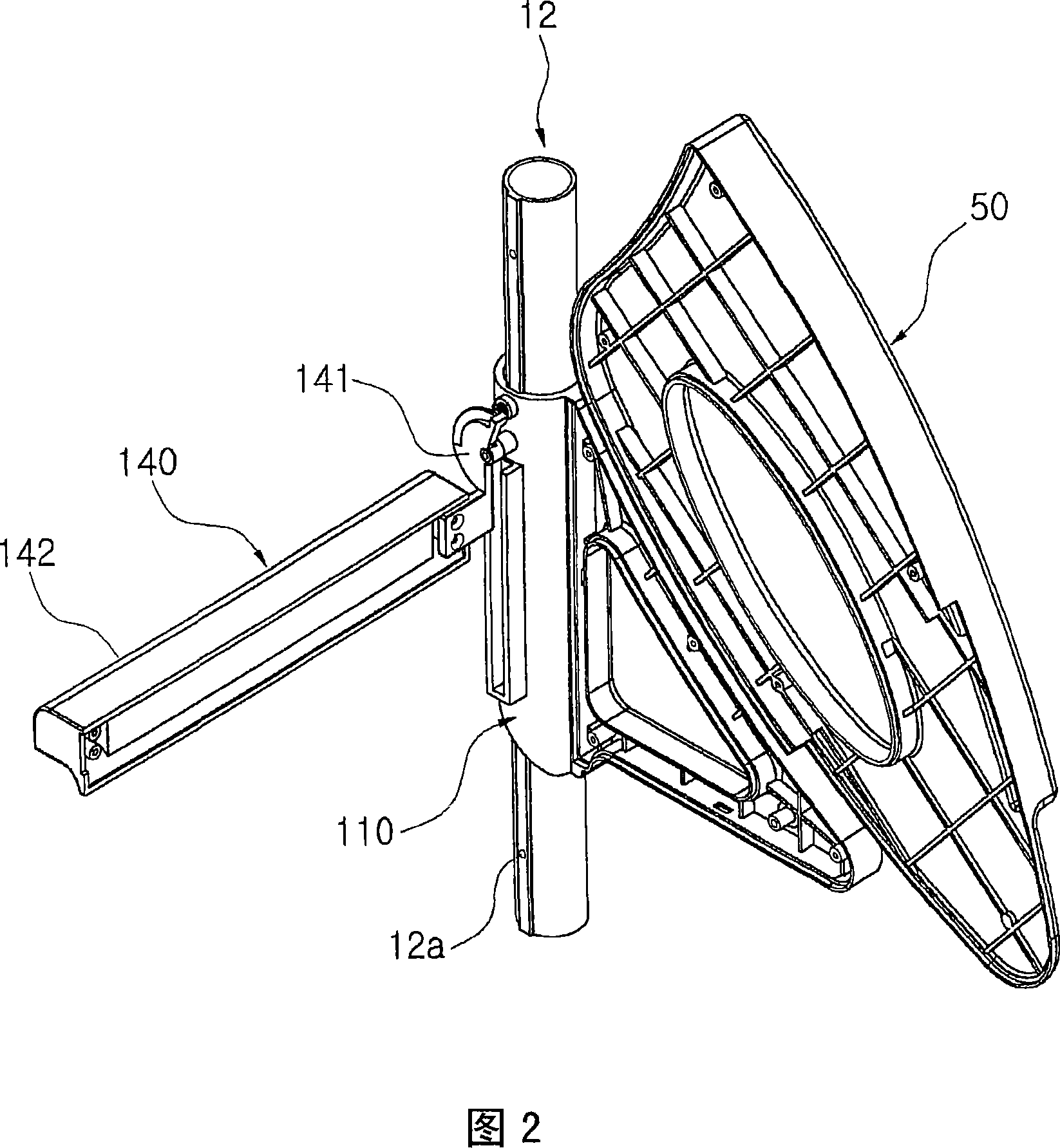
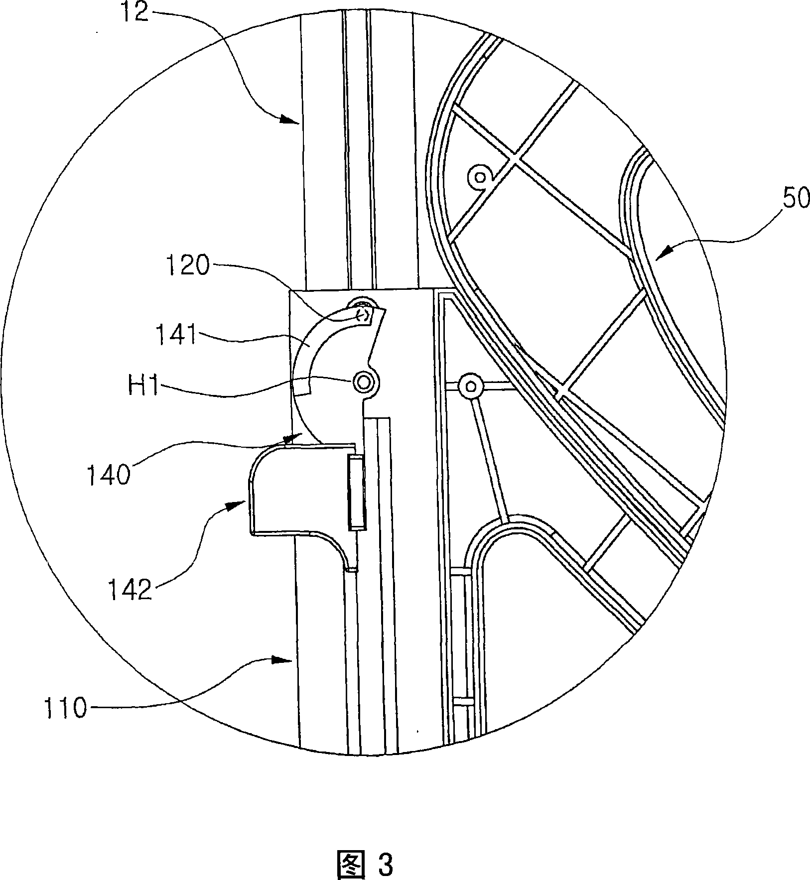
[0041] Referring to FIG. 1, the chair according to the present invention includes: a pair of "∠"-shaped support frames 10; a seat 20; and a backrest 30. Each support frame 10 includes a rod-shaped support member 11 and a guide member 12 . The support member 11 is arranged horizontally and placed on the ground. The guide member 12 is obliquely arranged to form a predetermined angle with the support member 11 , and a plurality of locking holes 12 a are formed along the length direction of the guide member 12 . The support frames 10 are coupled by couplings 13 in a parallel manner to each other. The seat 20 is mounted to the support member 11 of the support frame 10 using the seat height adjusting device 100 so that the height of the seat 20 is adjustable. The backrest 30 is mounted to the support member 11 of the support frame 10 using the backrest height adjus...


PUM


Abstract

A miniature magnetic field sensor including a magnetic core which co-operates with at least one excitation coil and a detection coil. In the magnetic field sensor, the core is open and includes at least one bar having tapered ends. A method of fabricating the sensor is provided using microtechnology techniques.

Description

technical field [0001] The present invention relates generally to a chair, and more particularly, to a chair in which the heights of the seat and backrest can be adjusted independently. Background technique [0002] As is generally known, various types of chairs are used depending on the desired purpose of the chair. Chairs are typically divided into coaches and armchairs. Benches allow several people to sit together. Armchairs are designed to allow one person to sit on them. Especially, in the case of an armchair, various functions are provided to the chair so that the user feels more comfortable. [0003] Generally, a conventional armchair includes a seat that supports a user's buttocks and a backrest that supports a user's back. Further, the chair may have a headrest to support the user's head or armrests on which the user's arms rest. [0004] Also, everyone who uses a chair has a different body type. Therefore, in order to change the shape of the chair to suit the...

Claims


Application Information

Patent Timeline
IPC IPC(8): A47C3/20
CPCA47C3/20
Inventor 李秉哲
Owner 李秉哲
Learn More