Pulp axis take-off device of warp rebeaming machine

A pulp shaft and unwinding technology, which is applied in the field of parallel shaft machine pulp shaft unwinding device, can solve the problems of uneven tightness of the weaving shaft roll layer, unstable performance of the magnetic powder brake, uneven tension, etc., and achieve the effect of consistent tightness of the roll layer

Inactive Publication Date: 2007-10-31
YANCHENG TEXTILE MASCH CO LTD
View PDF0 Cites 10 Cited by
  • Summary
  • Abstract
  • Description
  • Claims
  • Application Information

AI Technical Summary

Problems solved by technology

Due to the unstable performance of the magnetic powder brake, it often leads to uneven tension of the warp yarn during the winding proce

Method used


Image

  • Pulp axis take-off device of warp rebeaming machine

Examples


Embodiment Construction

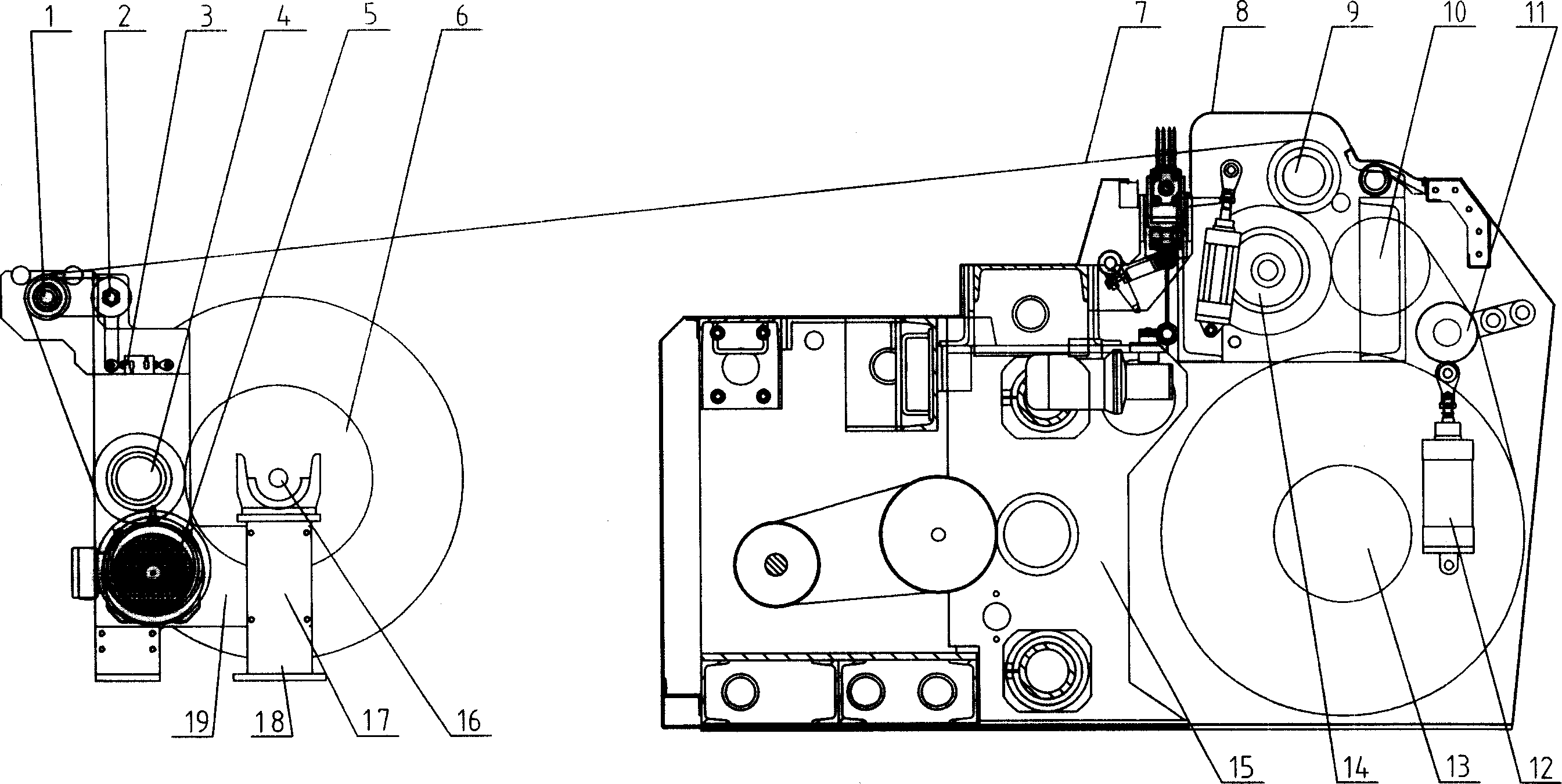
[0009] In the accompanying drawings, the present invention consists of an unwinding creel 18 and a head 15. Unwinding shaft frame 18 comprises bracket 17, paddle shaft 16, paddle shaft gear 6, intermediate gear 4, tension roller 1, support shaft 2, paddle shaft 16 is arranged on support 17, and one end of paddle shaft 16 is provided with paddle shaft gear 6 , the intermediate gear 4 meshes with the paddle shaft gear 6 and is arranged on the upper left side of the bracket 17, the motor reducer 5 is also arranged on the lower left side of the bracket 17, and the output shaft gear of the motor reducer 5 meshes with the intermediate gear 4 , the support shaft 2 is arranged on the upper left side of the bracket 17, the tension roller 1 is arranged on the support shaft 2 through the force arm, one end of the sensor force arm 19 is arranged on the support shaft 2, and the other end is connected with one end of the tension sensor 3, The other end of the tension sensor 3 is arranged on...


PUM


Abstract

The invention discloses a shaft reel off device of assembling machine, comprising a reel off shaft support and a machine head, wherein the reel off shaft support comprises a support, a shaft, a shaft gear, a middle gear, a tension roller via an arm is arranged on the support shaft, a support shaft, a tension sensor, a sensor arm, and motor reducer. One end of the sensor arm is arranged on the support shaft, while another end is connected with one end of the tension sensor, and another end of the sensor is arranged on the support, the motor reducer is arranged side under the middle gear while the output gear is meshed with the middle gear. The invention can hold constant tension in the reel process, to make constant force of reeled layer.

Description

Technical field [0001] The invention relates to a device mainly matched with a sizing machine and a water-jet loom for paralleling warp yarns of batches of beams after a sizing process, in particular to a beam unwinding device of a beam paralleling machine. Background technique [0002] The unwinding device of the parallel shaft machine is used in the pre-weaving weaving preparation project to complete the parallel shaft process. It is mainly matched with the sizing machine and the water jet loom, and is used for paralleling the warp yarns of batches of sizing shafts after the sizing process. The unwinding device of the parallel shaft machine usually consists of an unwinding shaft frame and a machine head. The unwinding shaft frame mainly includes the bracket, the paddle shaft, the paddle shaft gear, the intermediate gear, the tension roller, the support shaft, and the magnetic powder brake. It meshes with the intermediate gear; the machine head mainly includes the shell, ...

Claims


Application Information

Patent Timeline
IPC IPC(8): D02H5/02
Inventor 杭书高
Owner YANCHENG TEXTILE MASCH CO LTD
Why Eureka
Try Eureka