Method and system to indicate a logical grouping

一种逻辑关系、逻辑的技术,应用在指示逻辑分组和系统领域,能够解决移动、扰乱等问题

Inactive Publication Date: 2007-10-31
INT BUSINESS MASCH CORP
View PDF0 Cites 4 Cited by
  • Summary
  • Abstract
  • Description
  • Claims
  • Application Information

AI Technical Summary

Problems solved by technology

Thus, the positions of these text fields 104 cannot be moved just to simplify the flow of the line, as this would disturb the desired runtime composition, which is the main purpose of the application

Method used


Image

  • Method and system to indicate a logical grouping
  • Method and system to indicate a logical grouping
  • Method and system to indicate a logical grouping

Examples


Embodiment Construction

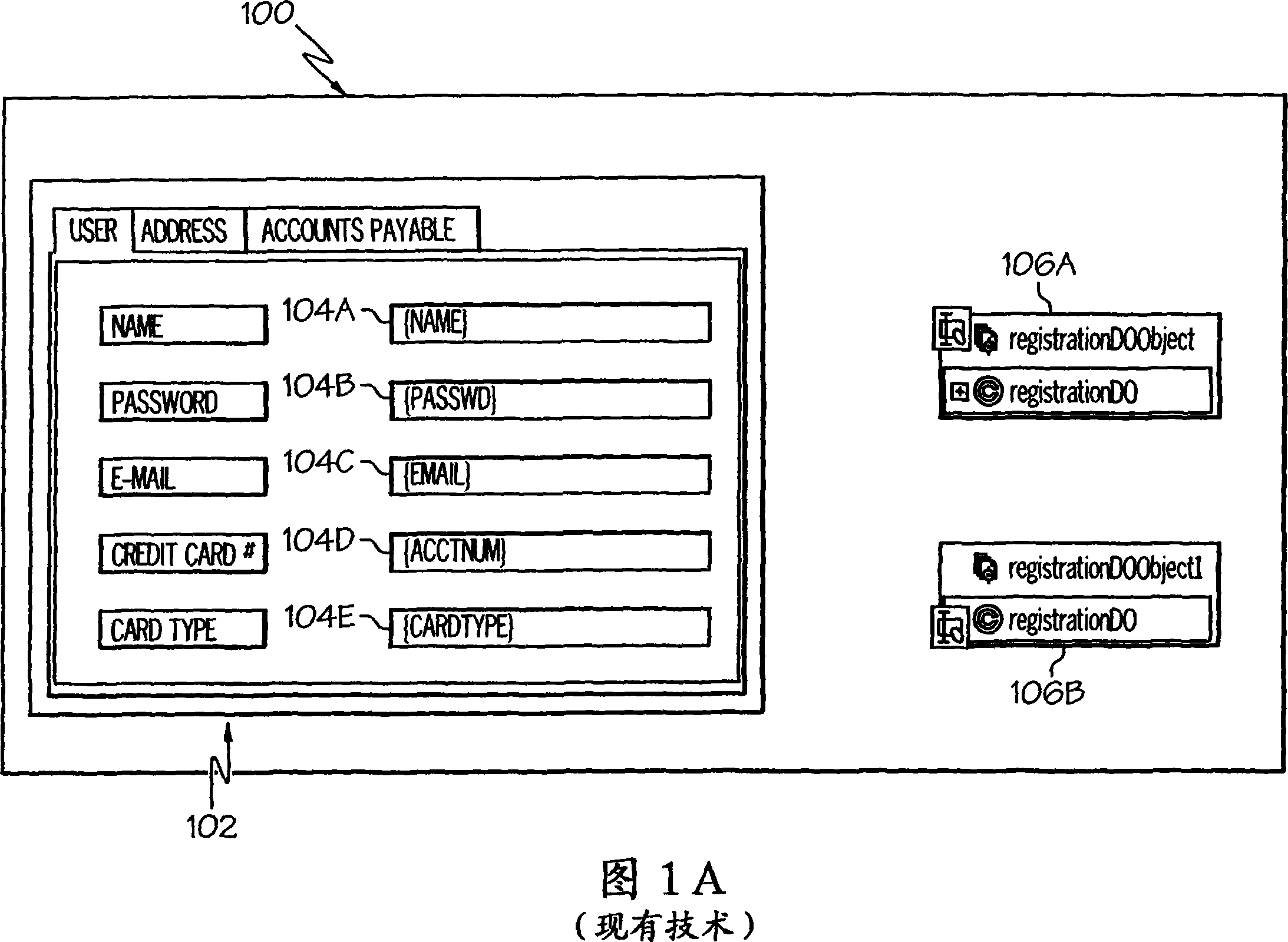
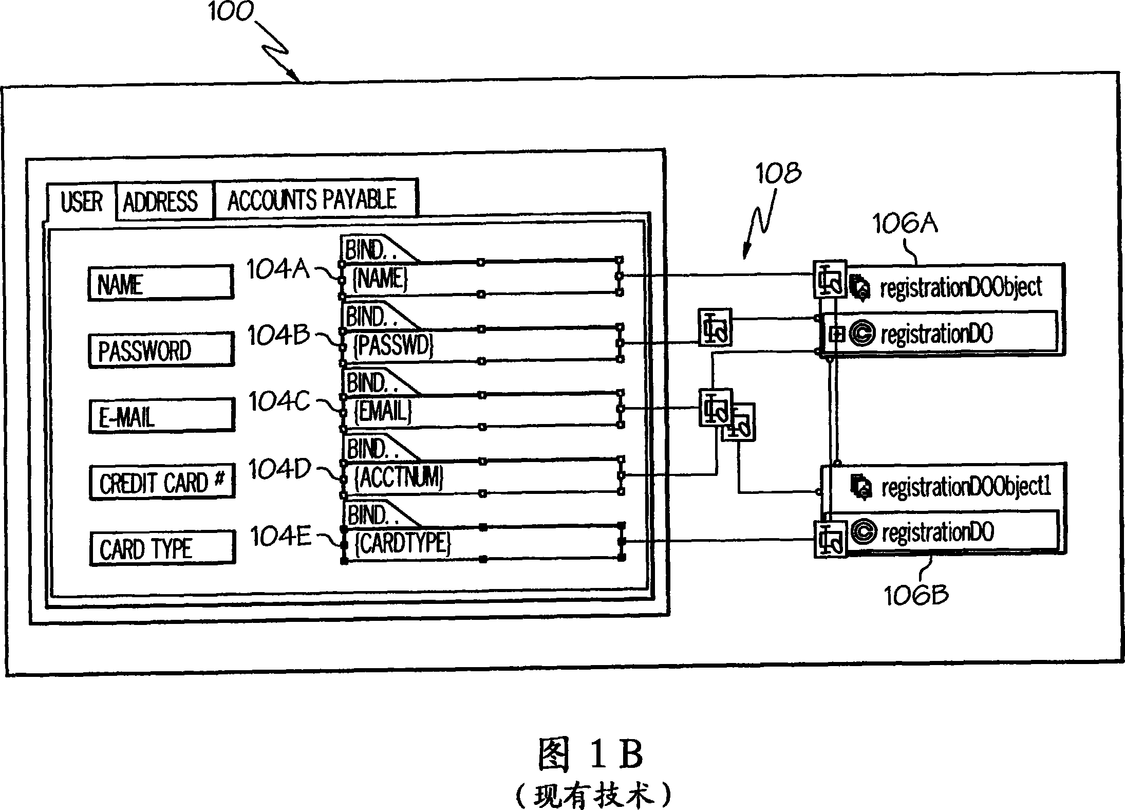
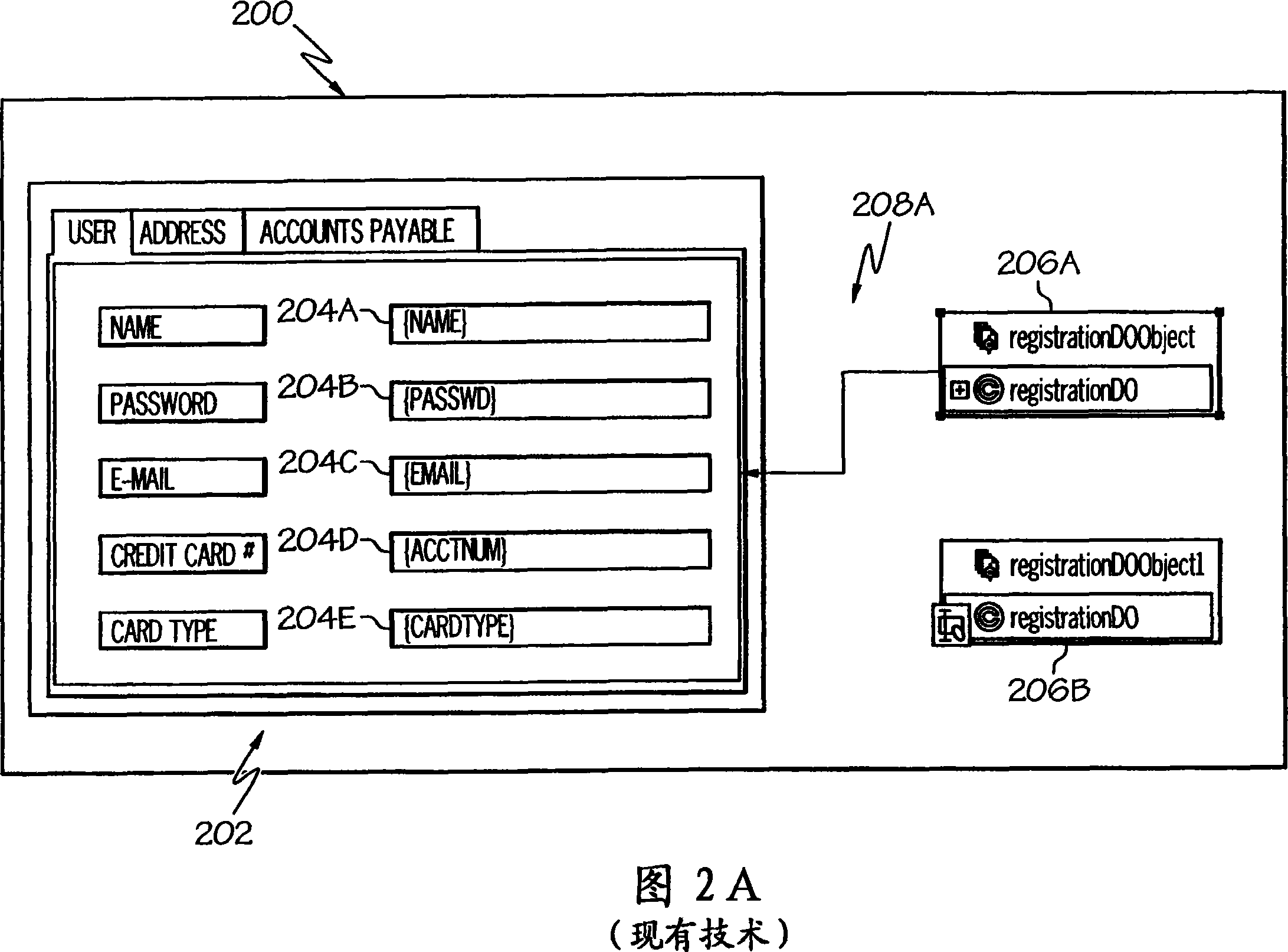
[0017] Referring now to FIG. 2a, the display 200 fields 204b, 204d and 204e corresponding to the entry areas of the respective "password", "acctnum" and "cardtype" maintain their normal colors when representing the object 206a, while the line 208a shows the object 206a is the base object for these fields. At the same time, fields 204a and 204c become (or, alternatively, remain) highlighted (grayed out). This selective highlighting of fields 204a and 204c is accomplished when data source object 206a is selected (eg, by clicking on the representation of 206a, or by selecting 206a from a drop-down menu (not shown)). This enables the user to select a shape and see what underlying objects are associated with it without drawing a large number of lines, which suffers from the problems described earlier. Additionally, clicking or otherwise selecting one of the fields 204 causes a line 208 to be automatically drawn to the appropriate object 206 . As shown in Figure 2b, if the user se...


PUM


Abstract

A method, apparatus and computer-readable medium for managing visual representations of relationships between active graphical areas such as text fields in a GUI and underlying software objects is presented. In one embodiment, the method includes the steps of receiving, by computer logic, a selection of an object graphical depiction of a data source software object, wherein the data source software object supports a field that is represented by a field graphical depiction in a Graphical User Interface (GUI); and in response to receiving the selection of the object graphical depiction, altering a physical appearance of the field graphical depiction, wherein altering the physical appearance of the field graphical depiction illustrates, in the GUI, a logical relationship between the data source software object and the field.

Description

technical field [0001] The present invention relates generally to the field of computers and similar technologies, and more particularly to software for use in this field. Background technique [0002] A graphical user interface (GUI) may present information to a user using graphs. This information may itself be part of the underlying model of the data, such as a set of nodes and arcs, or it may be a software tool that uses shapes to show the underlying object's data The runtime representation of the model. For example, the display 100 shown in FIG. 1a depicts a deployment diagram 102 (which includes a text field 104a for entering "name" data, a text field 104b for entering "password" data, a text field for Enter text field 104c, etc. for "email" name data and base software objects 106a-b. There is a logical relationship between text fields 104a-e and specific software objects 106a-b. Part of using the application may involve illustrating a set of such relationships to t...

Claims


Application Information

Patent Timeline
Patent Type & Authority Applications(China)
IPC IPC(8): G06F9/44
CPCG06F3/0482G06F9/4443G06F3/04817G06F3/0481G06F9/451Y10S707/99943
Inventor G·门德尔J·R·温切斯特
Owner INT BUSINESS MASCH CORP
Why Eureka
Try Eureka