Device and method for changing the reel in an unwinder

A technology of uncoilers and reels, which is applied in the directions of coiling strips, transportation and packaging, and thin material processing, etc., which can solve the problems of complex machinery and functions of uncoilers, and achieve simple machinery and functions, simple equipment manufacturing, and equipment economical effect

Inactive Publication Date: 2007-10-31
FUTURA SPA
View PDF5 Cites 2 Cited by
  • Summary
  • Abstract
  • Description
  • Claims
  • Application Information

AI Technical Summary

Problems solved by technology

However, these known uncoilers are mechanically and functionally very complex

Method used


Image

  • Device and method for changing the reel in an unwinder
  • Device and method for changing the reel in an unwinder
  • Device and method for changing the reel in an unwinder

Examples


Embodiment Construction

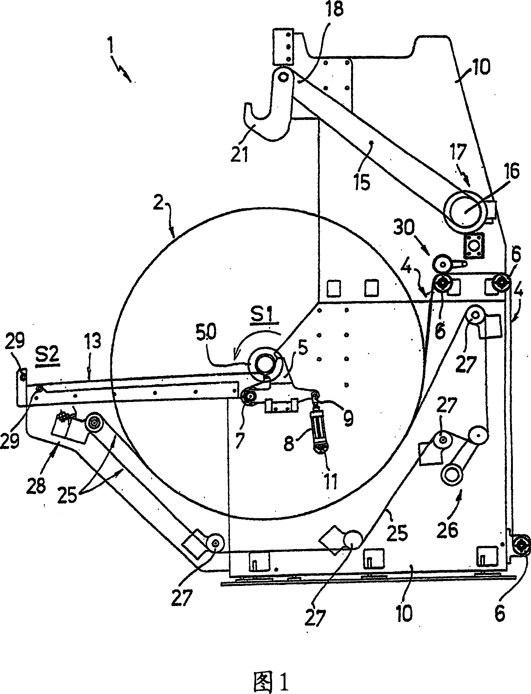
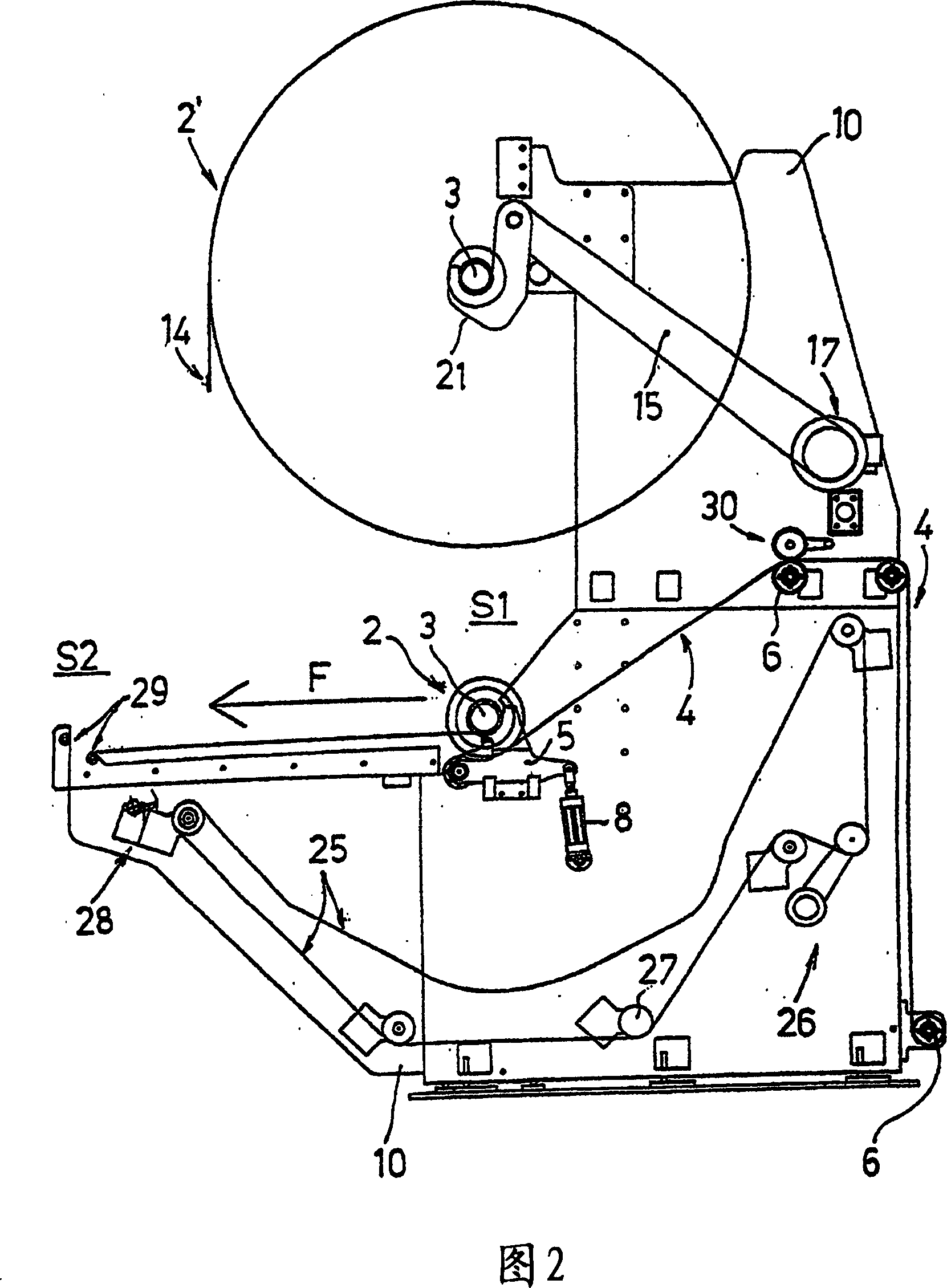
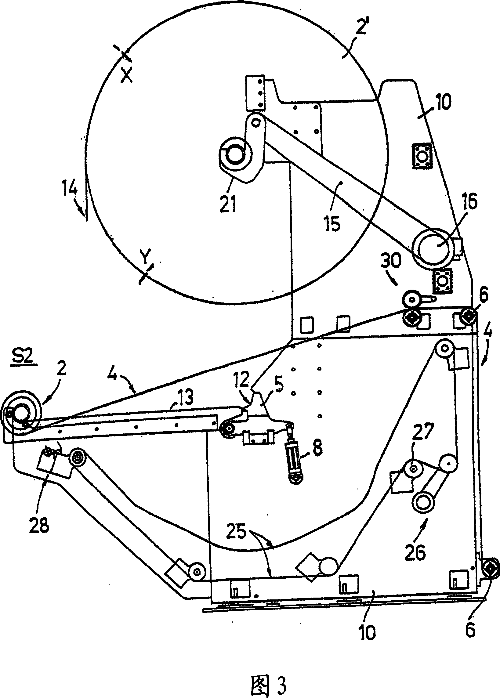
[0016] In the figures, reference numeral 1 generally designates a possible embodiment of the uncoiler according to the invention. In the continuation of this text, the words "upstream" and "downstream" refer to the direction in which the web advances (towards the right in the drawing). Also, the term "terminating portion or trailing end" defines the portion of the spool web that is being terminated, which portion is obtained by cutting and is intended to be joined to the initial or "head or end" of the spool web that is to replace the portion that is being terminated .

[0017] The uncoiler 1 is provided with a pair of conical supports, of the same type as those used in conventional uncoilers and adapted to engage, during the unwinding of the reel 2, two blades inserted from opposite sides of the core 3 of the reel. a spindle 50, thereby defining a horizontal axis about which the reel itself is free to rotate. In other words, between said support cones is defined a station o...


PUM


Abstract

The invention is to obtain the automatic change of the reel in an unwinder, in particular for reels of paper and other materials in web form, operation in which a reel (2) that is nearly empty is replaced with a new reel (2'), wherein provision is made to connect a tail portion (LC) of the web of the nearly empty reel (2) to the head portion (LT) of the web of the new reel (2') after overlapping of said ends (LC) and (LT), said overlap step begins along the surface of the new reel 2', right next to the latter.

Description

technical field [0001] The present invention relates to a device and a method for changing the spools of an unwinder, which can be used in particular for pad spools and other web-shaped materials. Background technique [0002] As is known, the function of an uncoiler is to unwind the coil from a reel for delivery to one or more machines downstream of a defined work cycle. In a possible known configuration, the uncoiler comprises a support structure on which two conical supports are arranged to engage with corresponding two mandrels inserted along both sides into a tubular core in the center of the pad reel, Also called "core", so that the spool is free to rotate about the respective axis and allows free unwinding of the respective web. [0003] A relatively important phase in the use of an uncoiler is the reel change, the operation of replacing an almost empty reel with a new one. It must be ensured that this operation of continuously feeding the coils to the machines loca...

Claims


Application Information

Patent Timeline
Patent Type & Authority Applications(China)
IPC IPC(8): B65H19/18B65H16/06B65H19/12
CPCB65H19/12B65H19/1836B65H16/06B65H2301/41361
Inventor 斯特凡诺·彼得里
Owner FUTURA SPA
Why Eureka
Try Eureka