Coal-cutting machine

A technology of coal cutting machine and cutting head, which is applied in the direction of slitting machinery, earth-moving drilling and mining, etc., can solve the problems of reducing the structure size, difficult to achieve rigidity and firmness, etc.

Active Publication Date: 2007-10-31
SANDVIK MINING & CONSTR OY
View PDF4 Cites 6 Cited by
  • Summary
  • Abstract
  • Description
  • Claims
  • Application Information

AI Technical Summary

Problems solved by technology

[0004] In machines with a particularly low structure, it is difficult to ach...

Method used


Image

  • Coal-cutting machine
  • Coal-cutting machine
  • Coal-cutting machine

Examples


Embodiment Construction

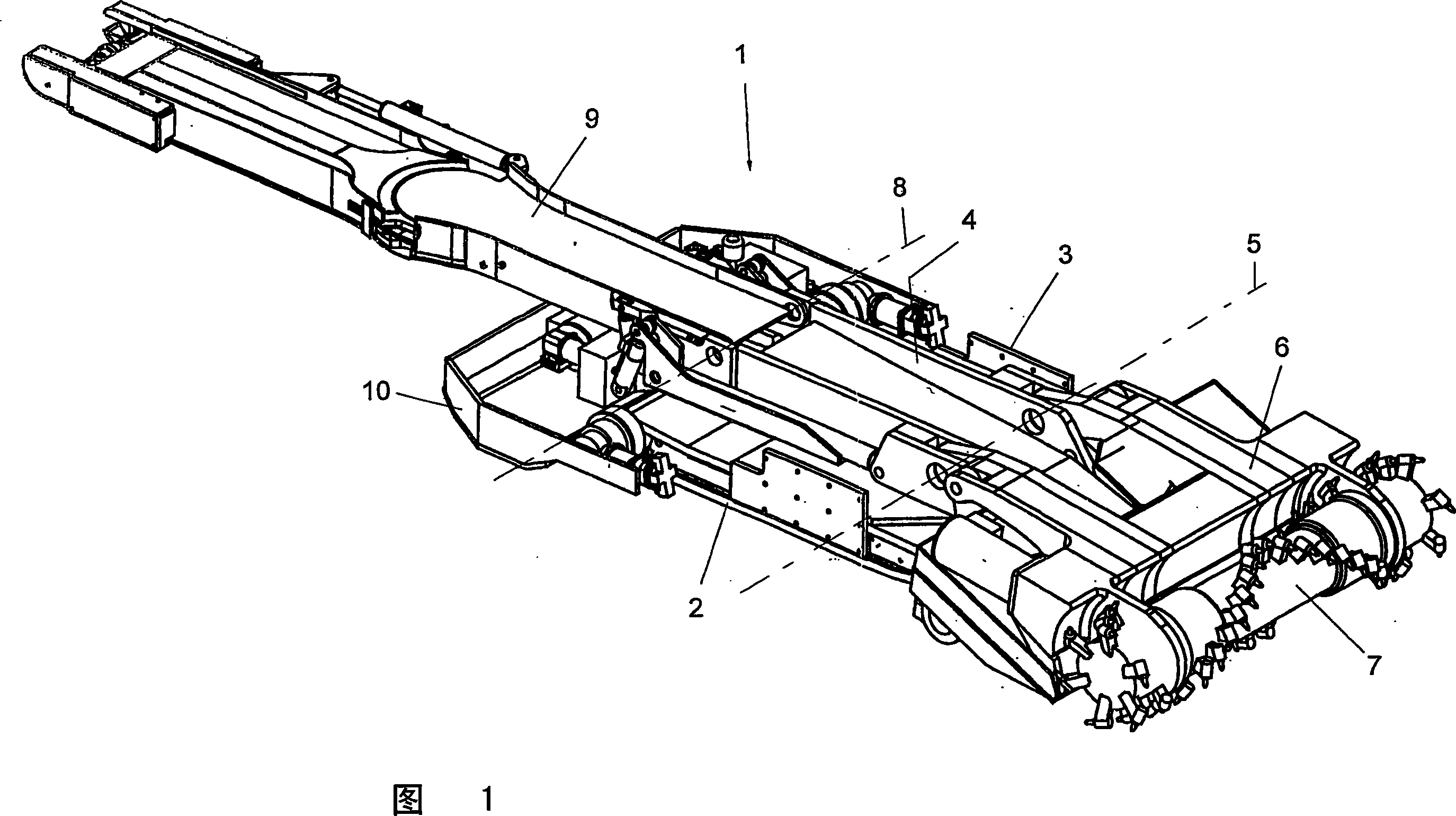
[0015] FIG. 1 shows a boring machine 1 with a crawler chassis 2 connected to a machine frame 3 . On this frame, a slide 4 is displaceable in the longitudinal direction of the machine, wherein the cantilever or cutting disc 6 with the rotatably mounted cutting drum 7 is pivotable in the height direction about a horizontal axis of rotation schematically indicated at 5 The way is hinged on the sliding seat 4.

[0016] The carriage 4 has an upwardly open groove-like contour, on the rear end of which carriage 4 a further frame part 9 is arranged so as to be deflectable about an axis of rotation 8 in the direction of height, by means of which Part 9, the conveyor belt supported in the groove, can be deflected in the height direction for adjusting the desired discharge height. On the frame 2, however, a further pivotable rear frame part 10 is arranged, which can be swiveled out sideways in curves, as will be explained in more detail in the following figures.

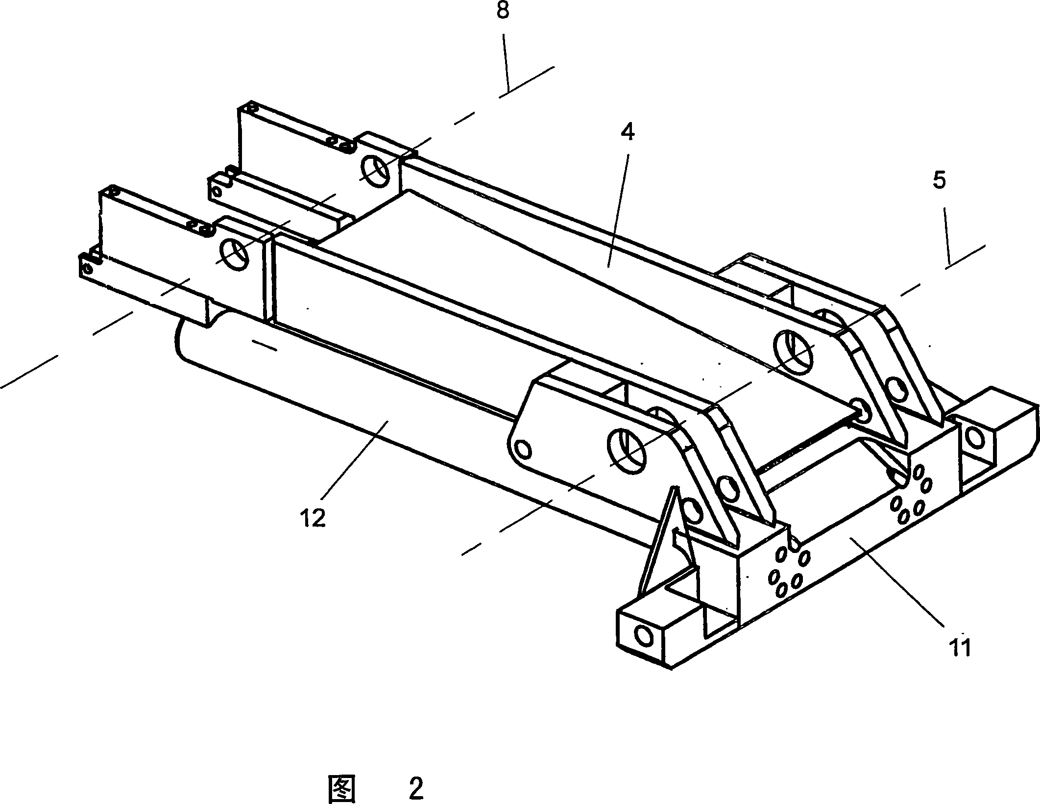
[0017] FIG. 2 shows a...


PUM


Abstract

The invention relates to a coal-cutting machine (1), with a cutting head or roller (7), mounted to rotate on a pivoting cutting arm (6) with a loading ramp or a conveyor (9), running in the direction of the face, for taking up and removal of the cut material, whereby the cutting arm (6) is mounted on a carriage (4) which may be displaced in guides, running in the machine longitudinal direction and said carriage (4) supports guide rods (12), running in the machine longitudinal direction which engage in tubular guides (13) of the machine frame (3), supporting a chassis (2).

Description

technical field [0001] The invention relates to a coal cutter with a cutting head or a cutting drum that can be mounted rotatably on a rotatable cutting disc, with a charging table or a cutting head facing the working face (Ortsbrust) A conveyor belt extending in the direction for receiving or conveying the cut material, wherein the cutting disc is supported on a slide that moves on guide rails extending in the longitudinal direction of the machine. Background technique [0002] In a coal cutter or roadheader, such as is known from AT 393295 B, the mining tool is movable on slides relative to a machine frame. In this known boring machine, a guide rod is arranged on the frame of the boring machine inside the crawler chassis, on which guide rod the carriage moves. For this purpose, the carriage has a tubular guide rail, wherein a corresponding displaceability along the guide rod is ensured in that the axial length of the tubular guide rail is shorter than the axial length of ...

Claims


Application Information

Patent Timeline
IPC IPC(8): E21C27/24
CPCE21C27/24
Inventor E·布兰德尔K·沙弗
Owner SANDVIK MINING & CONSTR OY
Why Eureka
Try Eureka