Door drive, in particular a revolving door drive

A drive device and door drive technology, applied in door/window accessories, power control mechanisms, switches with brakes, etc., can solve problems such as large structure width, achieve large piston area, increase piston displacement, avoid The effect of reducing work pressure

Active Publication Date: 2007-11-07
DORMAKABA DEUT GMBH
View PDF8 Cites 9 Cited by
  • Summary
  • Abstract
  • Description
  • Claims
  • Application Information

AI Technical Summary

Problems solved by technology

However, due to the large structural width it is not possible to fit in standard profiles

Method used


Image

  • Door drive, in particular a revolving door drive
  • Door drive, in particular a revolving door drive

Examples


Embodiment Construction

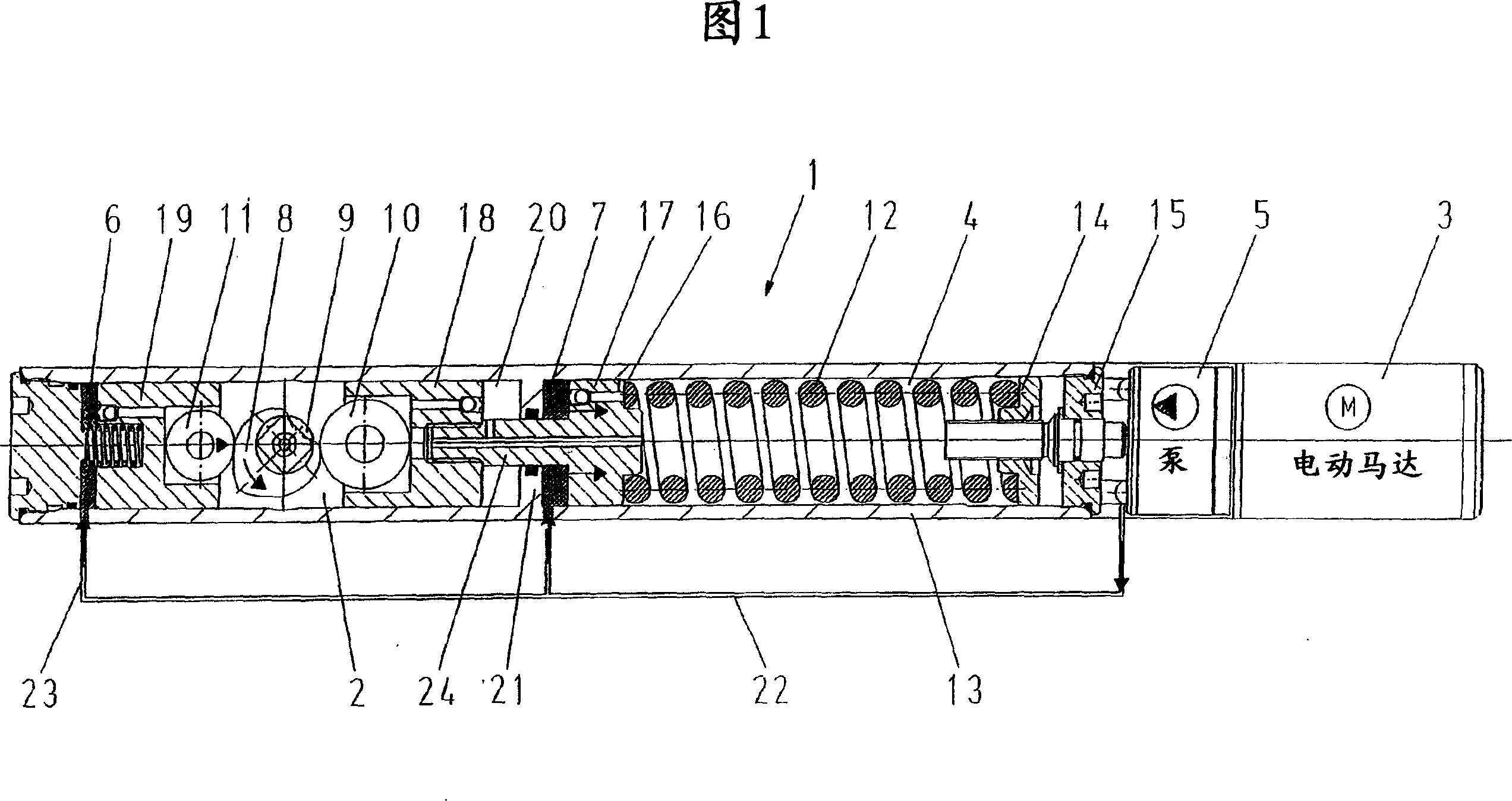
[0022] FIG. 1 shows a door operator 1 according to the invention, which can in particular be designed as a revolving door operator. Door drive device 1 has a drive unit 2, and it can be connected with the door not drawn in Fig. 1 (for example by a lever and slide rail and slide block) by output shaft 9, and drive unit 2 is arranged in a housing 13 .

[0023] Secondly, the door operator 1 has a motor 3 and a spring energy store 4 housed in a housing 13 , which is connected to the motor 3 and the drive unit 2 .

[0024] As shown in FIG. 1 , the motor 3 is drive-connected to a hydraulic pump 5 , in the embodiment shown the motor 3 and the pump 5 are flanged to a housing 13 . It is also conceivable that the motor 3 and the pump 5 are installed separately or integrated in the housing 13 . The motor 3 is hydraulically connected via a hydraulic pump 5 and a first hydraulic line 22 to a pressure chamber 7 which is associated with the spring accumulator 4 . The motor 3 and the pump ...


PUM


Abstract

An ink jet printer is provided with an ink jet head, a wiper and a transferring device. The ink jet head has an ink discharging plane. A plurality of ink openings for discharging ink toward a print medium and a liquid opening for discharging liquid are formed on the ink discharging plane. The ink openings are closer to one end of the ink discharging plane than the liquid opening is. The liquid opening is closer to the other end of the ink discharging plane than the ink openings are. The wiper wipes the ink discharging plane of the ink jet head. The transferring device transfers the ink jet head and / or the wiper such that the wiper wipes the ink discharging plane from a beginning position located at the other end side of the ink discharging plane to a finishing position located at the one end side of the ink discharging plane. The liquid discharged from the liquid opening adheres to the wiper when the wiper wipes an area where the liquid opening is formed. A distance between the liquid opening and an ink opening located at the most upstream position of the wiping direction of the wiper is longer than a distance between the two adjacent ink openings.

Description

technical field [0001] The invention relates to a door operator, in particular a revolving door operator, according to the preamble of claim 1 . Background technique [0002] A door operator is known from DE 295 21 068 U1. From DE 40 38 720 C2 an upper door lock with a sliding rail lever is known which has a cam drive unit which enables an optimum door torque curve and operating comfort. Therefore, this upper door lock is also suitable as a door pivoting device in principle, but the tests carried out within the scope of the present invention have obtained that when the oil pressure is applied to the drive unit, the hydraulic pressure is very unfavorably converted into a lifting-rotating motion and a new lifting movement. Since approximately 75% of the applied power is required for tensioning the spring accumulator of such a door lock, only approximately 25% of the power is delivered from the system for the acceleration of the door. Secondly, since it is desirable to maint...

Claims


Application Information

Patent Timeline
Patent Type & Authority Applications(China)
IPC IPC(8): E05F3/10E05F15/04
CPCE05F15/04E05F3/104E05F3/223E05Y2900/132E05F15/53
Inventor V·比内克
Owner DORMAKABA DEUT GMBH
Why Eureka
Try Eureka