Dual band antenna feeding

A dual-band antenna and feeding technology, applied in the directions of antennas, resonant antennas, antenna components, etc., can solve the problems of time-consuming, difficult replacement, etc., and achieve the effect of easy installation

Inactive Publication Date: 2007-11-07
POWERWAVE TECH SWEDEN AB
View PDF2 Cites 9 Cited by
  • Summary
  • Abstract
  • Description
  • Claims
  • Application Information

AI Technical Summary

Problems solved by technology

Also, if one cable is defective or breaks, using multiple different cables makes its replacement difficult and time consuming

Method used


Image

  • Dual band antenna feeding
  • Dual band antenna feeding
  • Dual band antenna feeding

Examples


Embodiment Construction

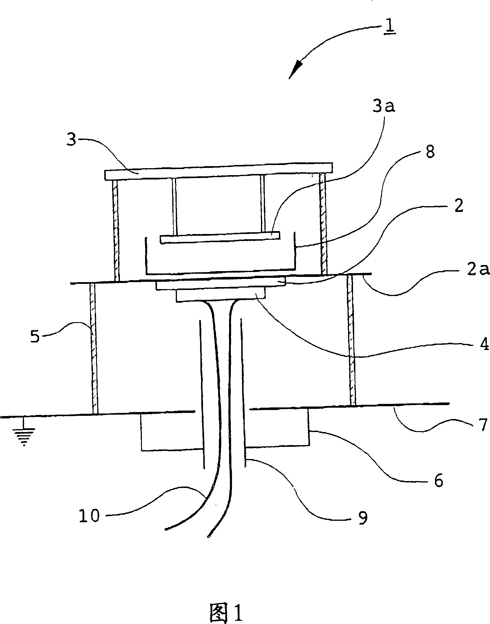
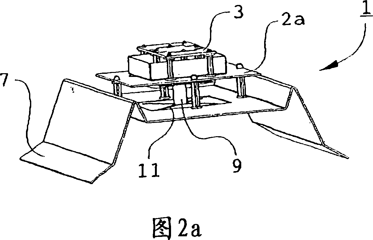
[0026] Referring first to FIG. 1 , there is shown a schematic diagram of a dual-band antenna according to the present invention. The dual-band antenna 1 is indicated generally by the reference numeral 1 . A first antenna element 2 is provided comprising a radiating element 2a, eg a patch, made of an electrically conductive material for radiating at a certain frequency. The antenna element 2 is placed at a distance of eg a distance 5 above the main reflector 7 , whereby the reflector 7 is arranged to reflect radiation from the first antenna element 2 . Preferably, a shielding box 6 is also provided to prevent reverse radiation. A second antenna element 3 comprising a radiating element 3 a is placed above the first antenna element 2 , and an auxiliary reflector 8 is provided for emitting radiation from the second antenna element 3 .

[0027] In its most general form, the invention is based on the idea of ​​using a shielded feed 9 through a first antenna element 2 to another an...


PUM


Abstract

The present invention is related to a dual band antenna 1 comprising a number of antenna elements for transmitting and / or receiving radio frequency radiation. The antenna elements are placed above each other, and a shielded feeding means 9 is provided through a first antenna element 2 to a second antenna element 3 for separately feeding the different antenna elements 2, 3.

Description

technical field [0001] The invention relates to a dual-band antenna of the type stated in the preamble of claim 1 . Background technique [0002] A typical dual-band antenna includes at least one first antenna element and an associated second antenna element for transmitting and / or receiving radio frequency radiation, and a conductive, substantially planar reflector device. The first and second antenna elements form a combined antenna element on the front side of the reflector device. Microwave power is usually fed in two separate frequency bands from a single feed network. The microwave power in the first frequency band is fed to the first radiation sheet through the aperture in the reflector device, and the microwave power in the second frequency band passes through the aperture in the reflector device and passes through the coupling sheet and ten in the first radiation sheet. The zigzag hole radially feeds power to the second radiation sheet. An example of such a prior...

Claims


Application Information

Patent Timeline
Patent Type & Authority Applications(China)
IPC IPC(8): H01Q9/04H01QH01Q1/48H01Q5/00H01Q9/36
CPCH01Q9/0414H01Q5/40H01Q1/526H01Q5/0072H01Q9/0428H01Q21/26H01Q9/0457
Inventor J·乌丁A·努德斯特伦B·林德马克
Owner POWERWAVE TECH SWEDEN AB
Why Eureka
Try Eureka