Leaky-wave antenna and beam forming method based on same

A beamforming method and leaky wave antenna technology, applied in leaky waveguide antennas, circuits, etc., can solve the problems of complex beamforming algorithms and difficult implementation, and achieve the effects of simple design, simple feeding, and improved input characteristics

Active Publication Date: 2016-06-29
BEIJING JIAOTONG UNIV
View PDF1 Cites 3 Cited by
  • Summary
  • Abstract
  • Description
  • Claims
  • Application Information

AI Technical Summary

Problems solved by technology

[0004] The purpose of the present invention is to provide a leaky-wave antenna and a beamforming method based on the leaky-wave antenna, which solves the problems of complex and difficult implementation of the existing beamforming algorithm, and at the same time expands the application occasions and scope of the leaky-wave antenna

Method used


Image

  • Leaky-wave antenna and beam forming method based on same
  • Leaky-wave antenna and beam forming method based on same
  • Leaky-wave antenna and beam forming method based on same

Examples


Embodiment 1

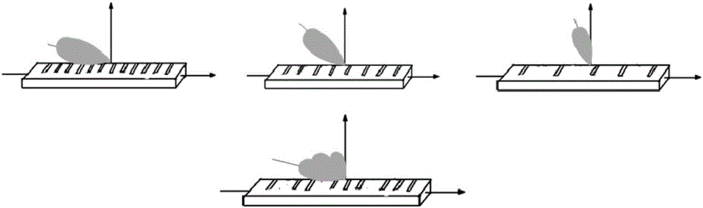
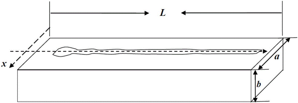
[0041] Such as figure 1 and figure 2 As shown, based on the rectangular waveguide wide-lobe leaky wave antenna of the present invention, the upper surface of the leaky rectangular waveguide is opened as follows image 3 The combined sine function shape gap shown; the width and height of the leaky rectangular waveguide are a=110mm and b=50mm respectively, the length of the waveguide is L=1000mm, and the working frequency is f=2.4GHz.

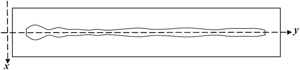
[0042] Such as image 3 As shown, the combined sine function-shaped slots are distributed along the y-direction of the central axis of the leaky rectangular waveguide. The combination type gap can be made up of 10 kinds such as Figure 4 The slits in the shape of a single-period sine function are superimposed according to combinations of different weighting coefficients. Period P of 10 single-period sine function-shaped gaps n and gap width W as a weighting factor n , and the corresponding pointing angle θ of the -1 space harmonic -1 As s...

Embodiment 2

[0052] Such as figure 1 and Figure 7 As shown, based on the substrate integrated waveguide wide-lobe leaky wave antenna of the present invention, the upper surface of the leaky rectangular waveguide is opened as follows Figure 8 The combined sine function shape gap shown; substrate integrated waveguide dielectric layer thickness h = 1.524mm, dielectric constant ε r = 3.0, the diameter of the metal through hole d = 1.0 mm, the center-to-center spacing s of adjacent metal holes on the same side = 1.7 mm, the width w of the substrate integrated waveguide = 22.15 mm, and the length L = 200 mm. The working frequency is f=5.8GHz.

[0053] Such as Figure 8 As shown, the combined sine function shape slot is divided along the y direction of the central axis of the leaky rectangular waveguide, and the combined slot is composed of 10 types such as Figure 9 The slits in the shape of a single-period sine function are superimposed according to combinations of different weighting coe...


PUM


Abstract

The invention discloses a leaky-wave antenna and a beam forming method based on the same. The shape of the leakage gap of the leaky-wave antenna adopts a composite structure including different periodic structures corresponding to different radiation directions. The leaky-wave antenna and the beam forming method based on the same have clear principle and simple design, so that the design and optimization of beam forming can be promoted.

Description

technical field [0001] The invention relates to the technical fields of electronics and communication. More specifically, it relates to a leaky wave antenna and a beamforming method based on the leaky wave antenna. Background technique [0002] In low-energy wireless communication and some specific applications, it is necessary to artificially plan the area and range of antenna radiation energy, such as expecting strong radiation in some directions of the antenna and weak radiation in other directions, or It is desirable to have stronger radiation in some larger angle ranges, etc., which requires the desired beamforming design for the radiation pattern of the antenna. Most of the existing antenna beamforming methods are based on the antenna array theory, using a more complex weighted array feeding method, but there is little research on the beamforming method of the leaky wave antenna with only one feeding port. [0003] Therefore, it is necessary to provide a leaky-wave a...

Claims


Application Information

Patent Timeline
Patent Type & Authority Applications(China)
IPC IPC(8): H01Q13/22
CPCH01Q13/22
Inventor 王均宏耿云杰
Owner BEIJING JIAOTONG UNIV
Why Eureka
Try Eureka