
A beam antenna based on heterogeneous heterogeneous medium

A special medium, non-uniform technology, applied in antennas, antenna unit combinations with different polarization directions, radiating element structures, etc., can solve problems such as difficult and complex pattern shaping, and achieve simple and easy engineering implementation. The effect of design freedom and low cost

Inactive Publication Date: 2016-06-01
SICHUAN UNIV
View PDF11 Cites 0 Cited by
  • Summary
  • Abstract
  • Description
  • Claims
  • Application Information

AI Technical Summary

Problems solved by technology

Traditional array shaping methods such as: Chebyshev polynomial method, Fourier transform method, Taylor method, Woodward method, etc., but these methods are difficult to complete the shaping of complex patterns

Method used


Image

  • A beam antenna based on heterogeneous heterogeneous medium
  • A beam antenna based on heterogeneous heterogeneous medium
  • A beam antenna based on heterogeneous heterogeneous medium

Examples


Embodiment 1

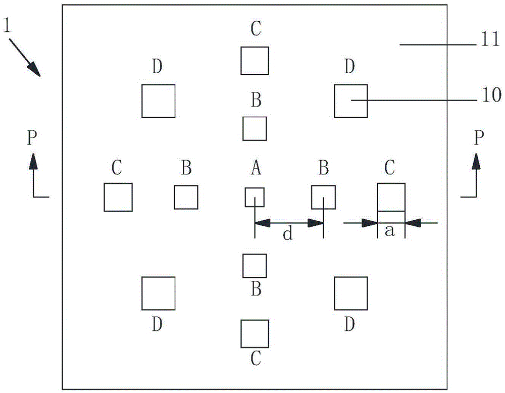
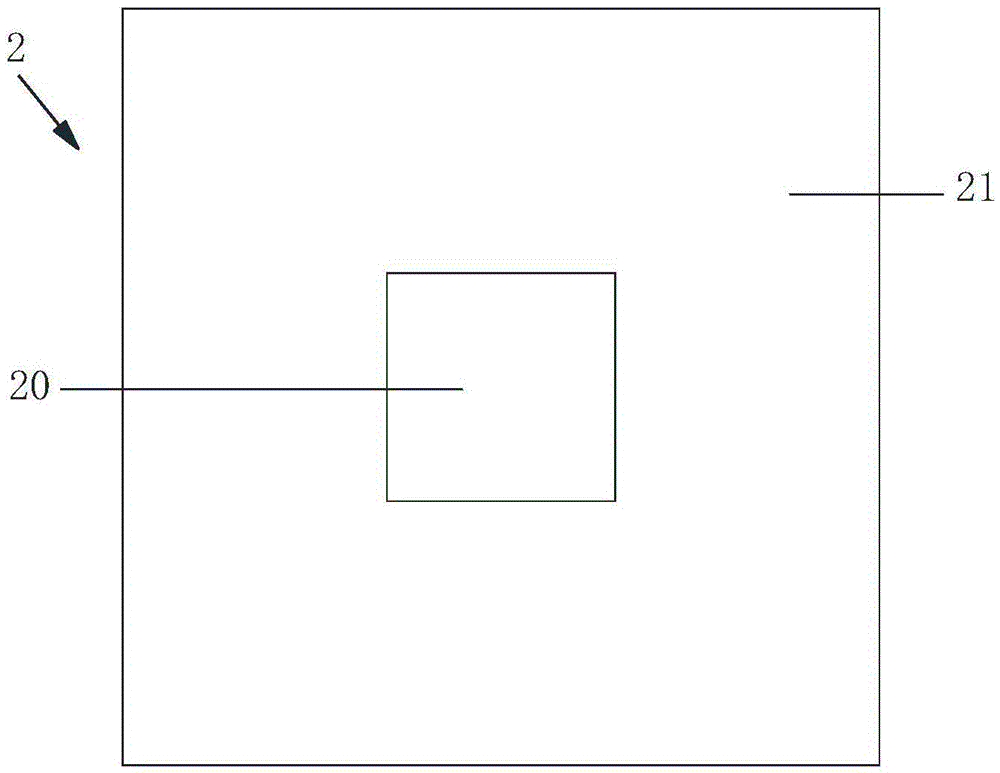
[0043] This example is based on a beam antenna with a non-uniform special medium, the structure is as figure 1 figure 2 with image 3 As shown, the radiator 2 and the shaping unit 1 are included. The function of the shaping unit of this example is to make the main lobe gain of the antenna beam uniform, that is, to form a high-quality beam, and basically does not affect the return loss and operating frequency of the radiator 2 and other performance indicators.

[0044] The shaping unit 1 in this example has a microstrip structure, consisting of a dielectric substrate 11 with a thickness of 0.5mm, a size of 80×80mm, and a dielectric constant of 2.65, and four square microstrip units of different sizes distributed on the surface of the dielectric substrate 11. 10, the microstrip unit 10 in this example is a microstrip patch, figure 1 Marked as square microstrip units A, B, C, and D, respectively, their side lengths a are 4.0mm, 4.8mm, 5.8mm, 6.9mm, and the center distance d between ...

Embodiment 2

[0048] In this example, the beam antenna structure based on the non-uniform special medium is as follows Figure 7 with Figure 8 As shown, the microstrip unit 10 adopts a microstrip gap, and the microstrip gap is a rectangular pattern formed by etching off the metal layer on the surface of the dielectric substrate 11 by using an etching process. The antenna of this example can also adjust the beam shape of the radiator by adjusting the shape, size, and position of the microstrip unit 10. The other structure of this example is the same as that of the first embodiment.

Embodiment 3

[0050] Such as Picture 9 As shown, this example is based on a beam antenna based on a non-uniform special medium, in which the microstrip unit 10 has a circular shape, which can be matched with a microstrip antenna using a circular radiating patch, by adjusting the diameter and distribution position of the microstrip unit. , Can change the beam shape of the radiator. The microstrip unit 10 of this example can also be a microstrip patch or a microstrip gap.

[0051] Among the shaping units described in the above embodiments, the common feature of the microstrip unit distribution is that microstrip units of different sizes are distributed on the dielectric substrate, and the distribution of these microstrip units is symmetrical about the center point, so that any two A vertical straight line divides the shaping unit into four parts with the same structure, such as Figure 10 ~ Figure 12 Shown. This distribution law can make the main lobe gain of the antenna beam uniform and form...


PUM


Abstract

The invention relates to the antenna shaping technology and discloses a high-quality beam antenna based on inhomogeneous specific media. The inhomogeneous specific media formed through a micro-strip structure are used for shaping an antenna pattern. According to the technical scheme, the high-quality beam antenna based on the inhomogeneous specific media comprises a radiator and a shaping unit. The shaping unit is placed in front of a radiation beam of the radiator, the shaping unit is of a micro-strip structure and is composed of a medium substrate and micro-strip units distributed on the surface of the medium substrate, and the shape of the beam of the radiator is adjusted according to the shape, the size and the position of each micro-strip unit. According to the high-quality beam antenna based on the inhomogeneous specific media, the shaping unit is composed of the medium substrate and the micro-strip units distributed on the surface of the medium substrate, so that the high-quality beam antenna has the characteristics of the inhomogeneous specific media. The shape of the beam of the radiator can be adjusted, the antenna pattern can be shaped in various ways, and the higher design freedom degree is provided for the high-quality beam.

Description

Technical field [0001] The present invention relates to antenna shaping technology, in particular to a beam antenna based on a non-uniform special medium. Background technique [0002] In microwave application technology, the transmission and reception of microwaves are inseparable from antenna systems, such as microwave communication, microwave detection, and microwave wireless energy transmission. Different application fields have different requirements for antenna systems. [0003] Microwave wireless energy transmission uses microwave as a carrier, and transmits and receives microwave energy through an antenna to realize long-distance wireless energy transmission. It has broad application prospects in many fields such as space solar power stations. [0004] In the microwave wireless energy transmission system, the microwave energy transmitting antenna is one of the key equipment. The transmitting antenna is a high-gain directional antenna, which radiates a very narrow high-power ...

Claims


Application Information

Patent Timeline
Patent Type & Authority Patents(China)
IPC IPC(8): H01Q21/24H01Q1/38H01Q13/08
Inventor 陈星黄卡玛刘长军郭庆功杨阳赵翔闫丽萍杨晓庆陈倩
Owner SICHUAN UNIV
Learn More