Permanent power water-saving machine

A technology of power wheel and water inlet, which is applied to engine components, machines/engines, liquid fuel engines, etc., can solve problems such as power consumption, and achieve the effect of high efficiency and low cost

Inactive Publication Date: 2007-11-14
郭忠贤
View PDF1 Cites 5 Cited by
  • Summary
  • Abstract
  • Description
  • Claims
  • Application Information

AI Technical Summary

Problems solved by technology

[0002] At present, the water-saving devices disclosed on the Internet include automatic water-saving devices and patent No. CN9724595328.8. Its structure is that the motor drives the impeller on the shaft to lift the water to a certain height and store it for secondary use. The disadvantage is that it needs to consume electric energy to To achieve the purpose of saving water

Method used


Image

  • Permanent power water-saving machine
  • Permanent power water-saving machine
  • Permanent power water-saving machine

Examples


Embodiment Construction

[0013] The present invention will be further described below in conjunction with the accompanying drawings.

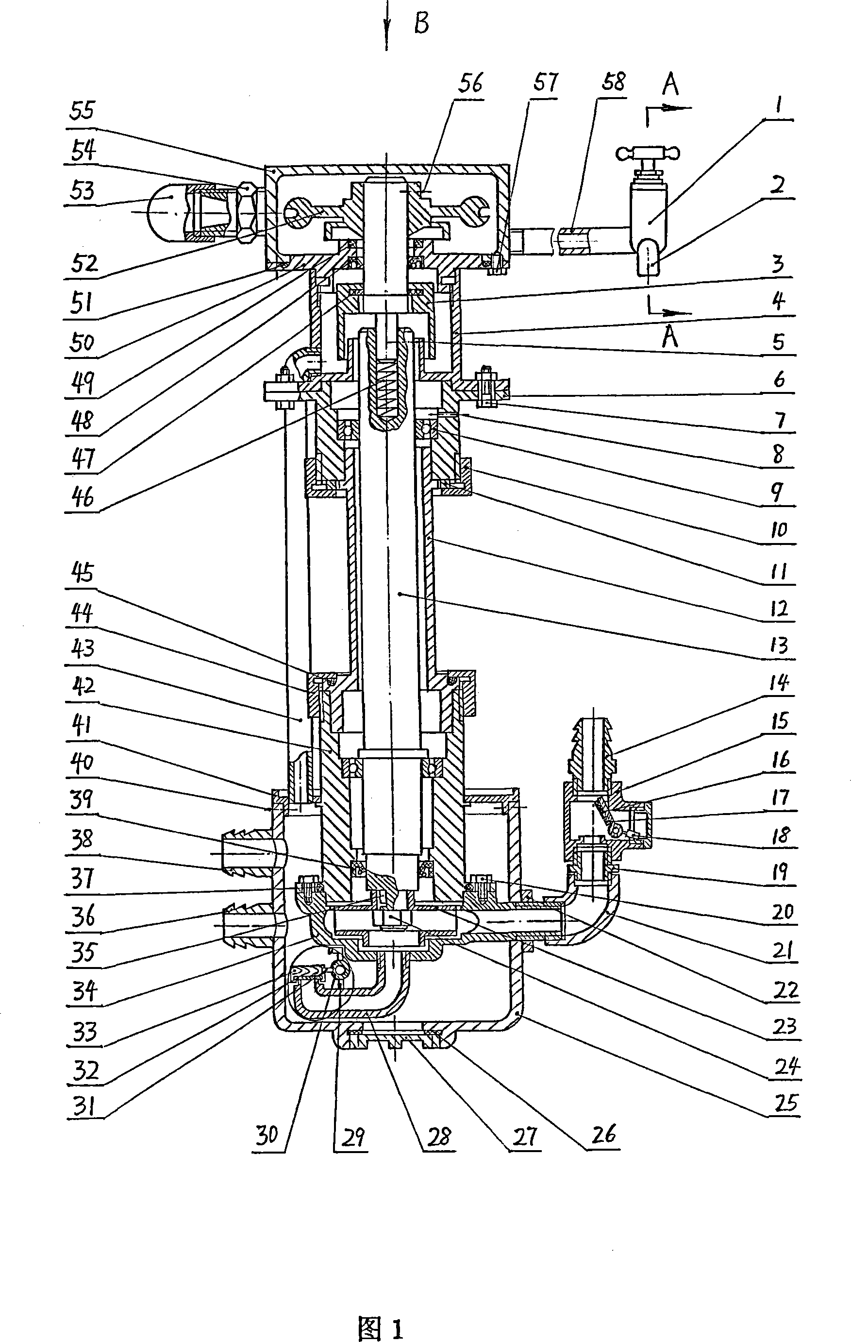
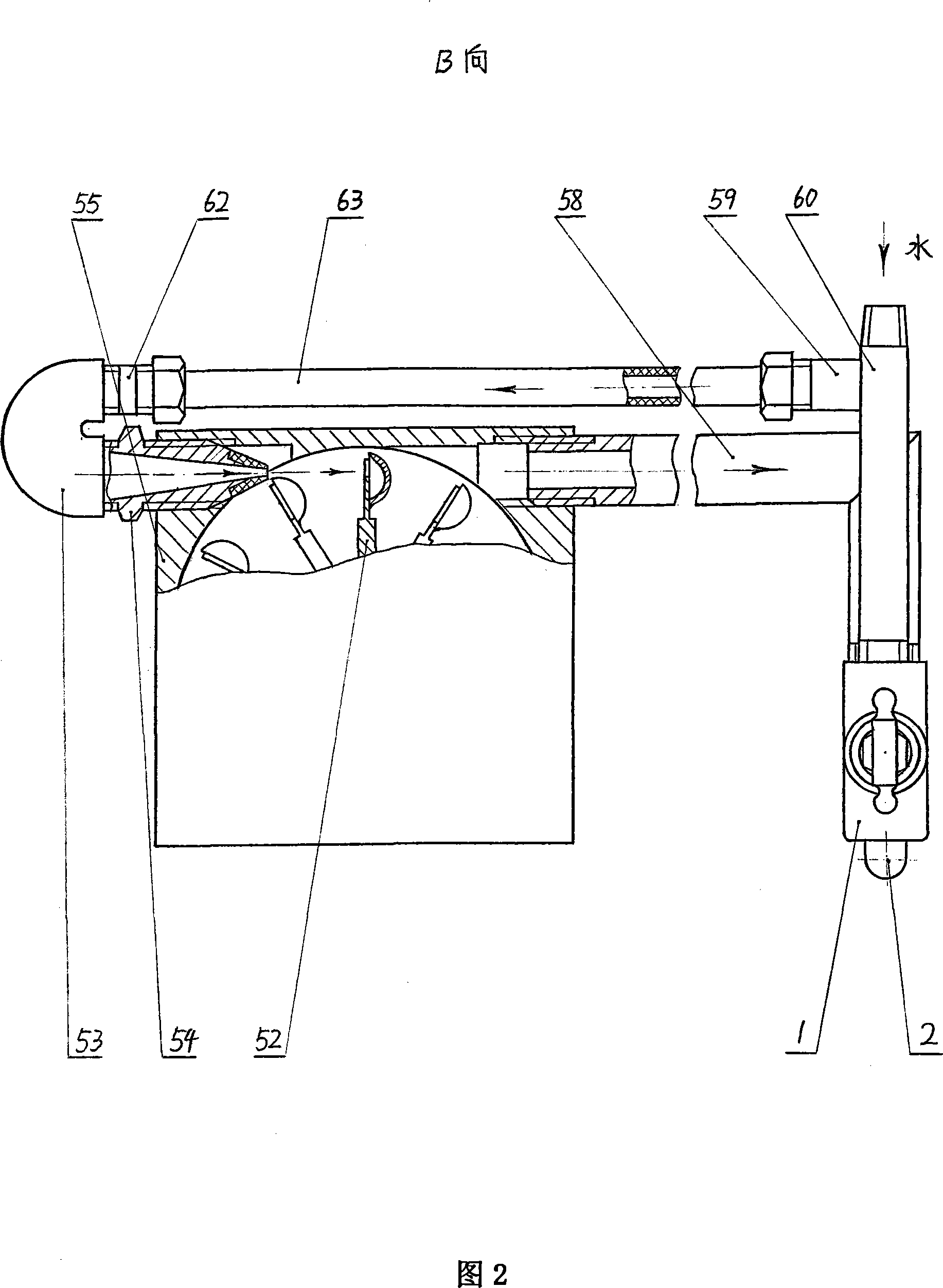
[0014] In Fig. 1, the water column coming out of the inner taper hole joint 54 impacts the power wheel 52 to rotate, and the power wheel 52 drives the coaxial impeller 23 to rotate, lifts the water to a certain height, and stores it for secondary use. This is its implementation principle. The water-saving machine is divided into 10 parts according to the structure and described separately.

[0015] 1. Faucet part

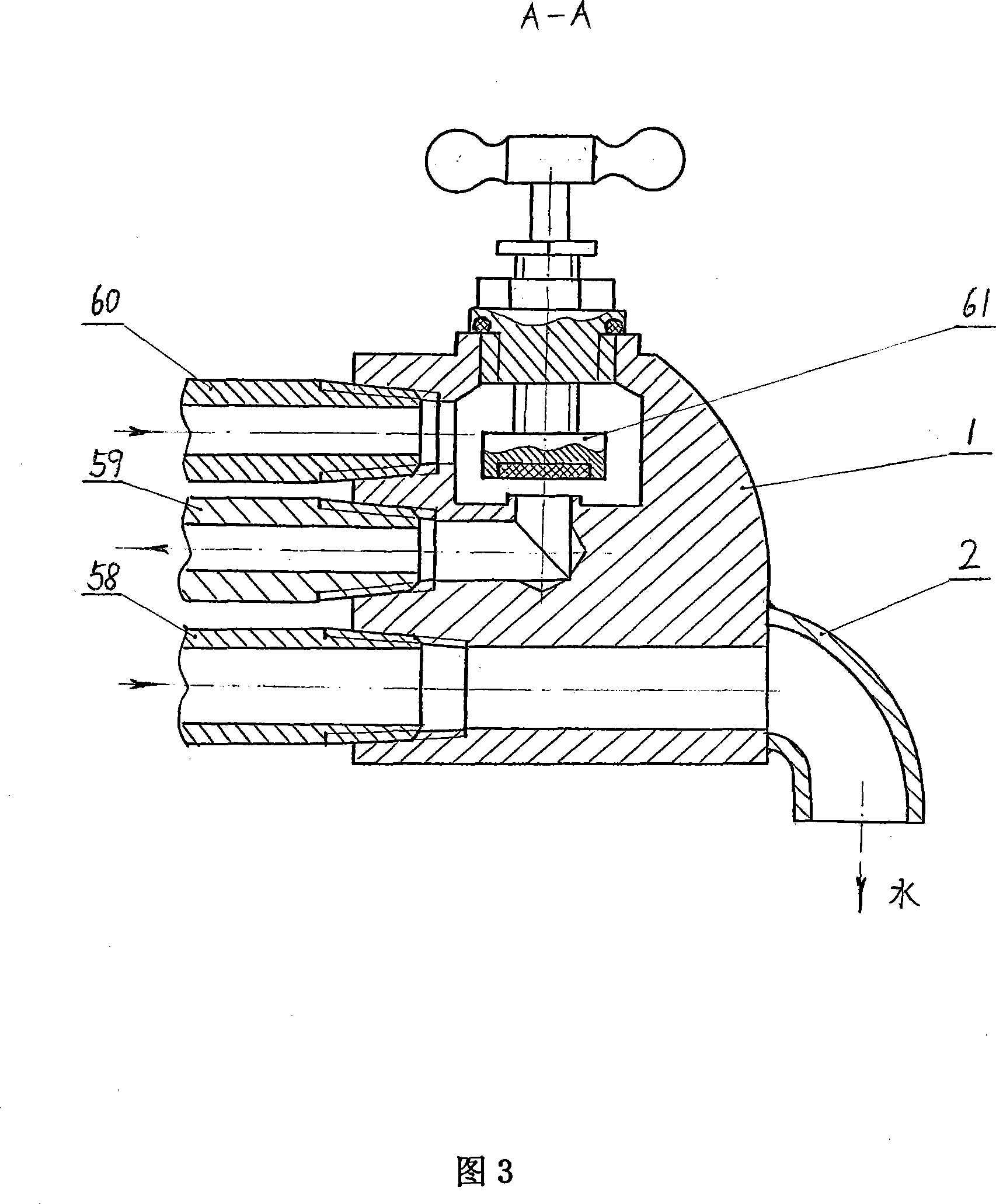
[0016] In FIG. 3 , the faucet part includes a faucet body 1 , a water outlet pipe 58 , a water inlet pipe 59 , a water supply pipe 60 , a valve core 61 , and a water outlet 2 . As can be seen in conjunction with Fig. 2, one end of the outlet pipe 58 is connected to the faucet body 1, and the other end is connected to the box body 55; Type elbow 53, inner tapered hole joint 54 link to each other with casing 55; One end of water supply pipe 60 is connected ...


PUM


Abstract

The invention discloses a save water machine without outside force, when opening the tap,it can save auto water.which consists of pump shell, impeller, axis frame, axis, driving wheel, vavle and reseroir. The driving wheel is in box which the inlet and outlet on, the inlet is flowed tap water provieded power to the driving wheel. The outlet is flowed water for everyday use after using afflux in the pump shell, the water is raised to one height by pump and reserved to reuse. Impeller of rim of the driving wheel has the shape of a bowl; outlet of the impeller has a breach cover. The inlet of the pump shell sets a choke valve consisting of syphon, float plate and caging device,the choke valve can prevent air from entering pump shell. The save water machine is used for all place with tap water,and now there are seres sample machine producing.

Description

technical field [0001] The invention relates to a device for saving water, in particular to a device for automatically saving water without external assistance. Background technique [0002] At present, the water-saving devices disclosed on the Internet include automatic water-saving devices and patent No. CN9724595328.8. Its structure is that the motor drives the impeller on the shaft to lift the water to a certain height and store it for secondary use. The disadvantage is that it needs to consume electric energy to To achieve the purpose of water saving. Contents of the invention [0003] The invention overcomes the deficiencies in the prior art and provides a fully automatic water-saving machine that can save water by turning on the faucet without the assistance of external force. [0004] In order to solve the above-mentioned existing technical problems, the present invention is achieved through the following technical solutions. [0005] The water-saving machine of ...

Claims


Application Information

Patent Timeline
IPC IPC(8): F04D13/04F04D29/24F04D29/42F04D29/66F03B13/00
Inventor 郭忠贤
Owner 郭忠贤
Why Eureka
Try Eureka