Method for estimating automatic focusing least effective sampling points

An automatic focusing and sampling point technology, applied in the direction of focusing devices, color TV parts, TV system parts, etc., can solve the problems of different lens characteristics and inability to focus accurately, and achieve the effect of reducing search time

Inactive Publication Date: 2007-11-14
PRIMAX ELECTRONICS LTD
View PDF0 Cites 14 Cited by
  • Summary
  • Abstract
  • Description
  • Claims
  • Application Information

AI Technical Summary

Problems solved by technology

However, the characteristics of each lens are different. For some lenses, the sampl

Method used


Image

  • Method for estimating automatic focusing least effective sampling points
  • Method for estimating automatic focusing least effective sampling points
  • Method for estimating automatic focusing least effective sampling points

Examples


Embodiment Construction

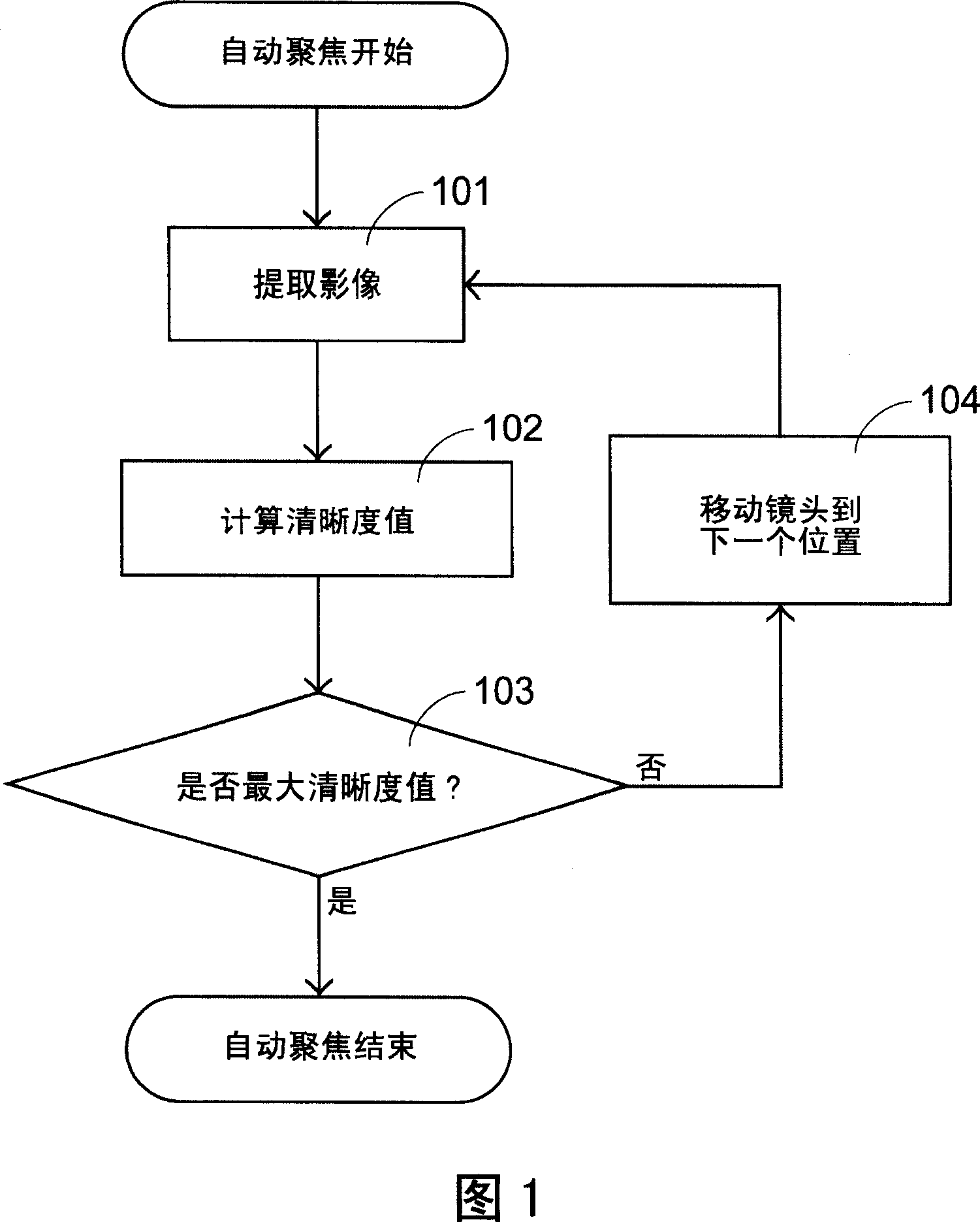
[0034] The present invention utilizes an image extraction device, such as a digital camera, to evaluate effective sampling points by utilizing the optical depth of field characteristic, so as to reduce the search time of autofocus.

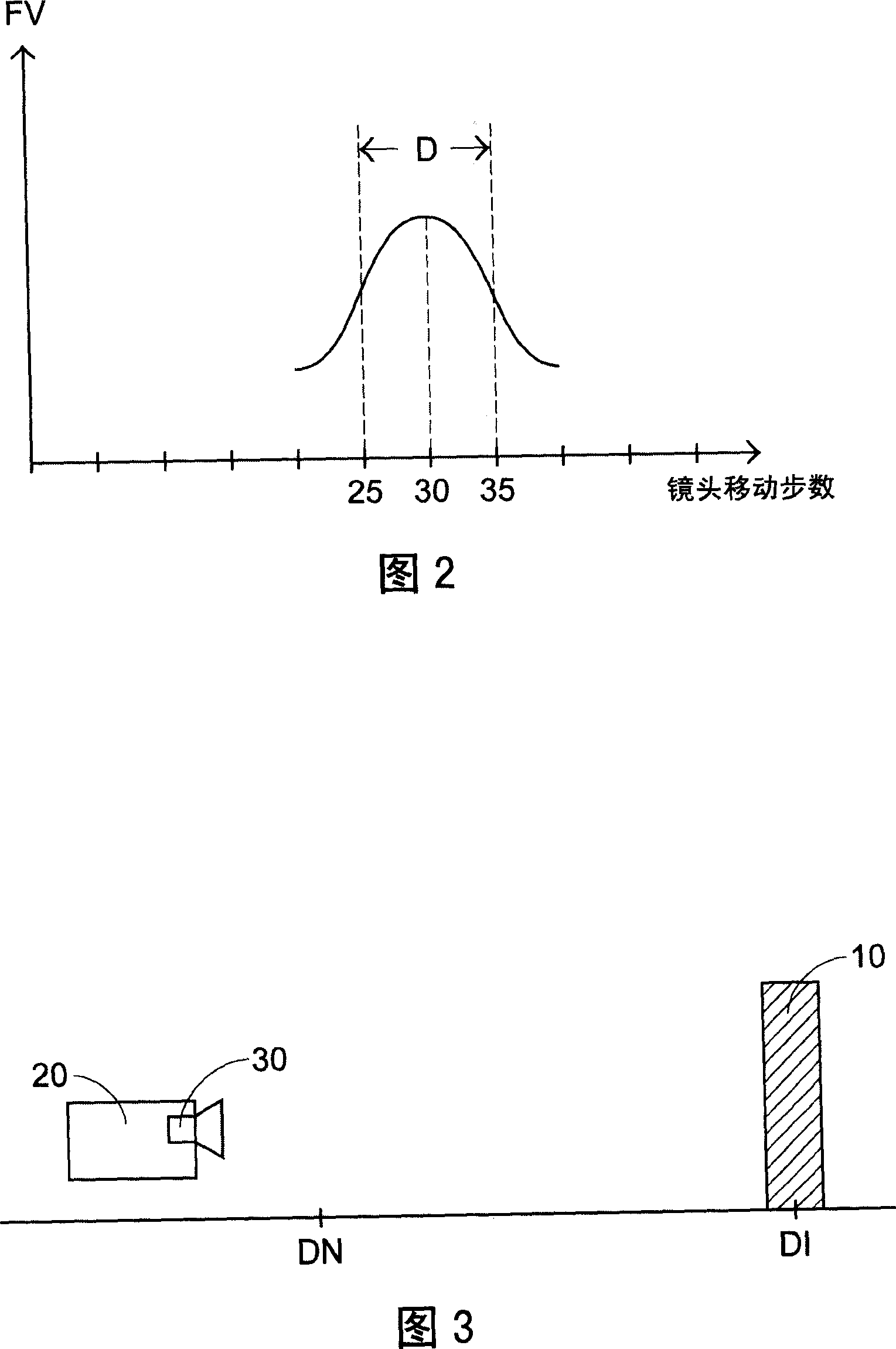
[0035] Please refer to FIG. 2 , which is a graph of the known focus value (FV) and the number of lens movement steps, wherein the horizontal axis is the number of lens movement steps, and the vertical axis is the corresponding sharpness value. As shown in Figure 2, there is a maximum sharpness value when the lens moves to the 30th step, but because the optical component has the characteristics of the depth of field, that is, the image obtained by the object within the depth of field range D can be regarded as clear, so at the 30th step The sharpness values ​​obtained in the depth of field range D corresponding to steps 25 to 35 all represent acceptable clear images. That is to say, there are 11 steps in the range D, and according to the known glob...


PUM


Abstract

The invention relates to an assessment autofocus effective sampling method. The invention of the use of depth of field, the focus test chart in a particular location of the biggest tests of clarity, based on a vague percentage of the value of the test should be the location of a depth of field boundary step, removed only with the greatest depth of field within the scope of the definition of Moves to search the depth of field borders corresponding step the focus of the test plans another test location, definition and calculation of its greatest value, and so on. This will be adopted within the scope of the majority of depth of field sampling neglect from which only a representative sampling point for the steps, but at least effective access to the most effective sampling point, thus reducing auto-focus the search time required.

Description

technical field [0001] The invention relates to a method for evaluating effective sampling points for automatic focusing, in particular to a method for evaluating sampling points for automatic focusing of an image extraction device. Background technique [0002] Products such as digital camera and camera phone have been very popular photographic equipment, and digital camera must focus on the correct object to obtain good photo quality. Therefore, the method of autofocus is very important for digital camera. [0003] General autofocus is roughly divided into active autofocus and passive autofocus. Since the active auto-focus requires an additional optical transmitter and receiver, which increases the cost of the digital camera, generally digital cameras use passive auto-focus. [0004] Please refer to FIG. 1 , which is a flow chart of passive autofocus. In the passive autofocus method, the lens is moved to different focus positions (that is, different lens positions or ste...

Claims


Application Information

Patent Timeline
IPC IPC(8): G03B13/36H04N5/225
Inventor 徐纬
Owner PRIMAX ELECTRONICS LTD
Why Eureka
Try Eureka