Camera-based heliostat calibration with artificial light sources

a technology of artificial light source and heliostat, which is applied in the direction of instruments, instruments for comonautical navigation, optical radiation measurement, etc., can solve the problems of poor nominal estimation of heliostat parameters and delay in the calibration process

Active Publication Date: 2010-02-11
SEPCOIII ELECTRIC POWER CONSTR CO LTD
View PDF9 Cites 58 Cited by
  • Summary
  • Abstract
  • Description
  • Claims
  • Application Information

AI Technical Summary

Benefits of technology

[0015]Method embodiments of the present invention include detecting one or more artificial light reflections such as curvilinear light source reflections, and that may be detected by an imaging sensor as a substantially contiguous group of discrete pixels or “blob,” in binary, or multi-bit format. Method embodiments of the present invention provide for more than 50 heliostat reflections processed simultaneously and independently at one or more two-dimensional imagers such as cameras. A reflection search and centering procedure of some method embodiments of the present invention may be based on a priori, e.g., survey-derived, engineering drawing derived, or otherwise known, geometry of the locus of detectable reflections in the heliostats configuration space, and the configuration space search process may comprise driving a heliostat in a single degree of freedom toward the locus, or in one or more alternate single-degree of freedom motions, or all degrees of freedom simultaneously. Some reflection search and centering procedure embodiments explore one or more f

Problems solved by technology

The set of heliostat configurations, e.g., in an ordered rotational pair of angles azimuth-elevation (az-el) or an unordered rotational pair of angles (tilt-tilt) space, which produce detectable reflect

Method used


Image

  • Camera-based heliostat calibration with artificial  light sources
  • Camera-based heliostat calibration with artificial  light sources
  • Camera-based heliostat calibration with artificial  light sources

Examples


Embodiment Construction

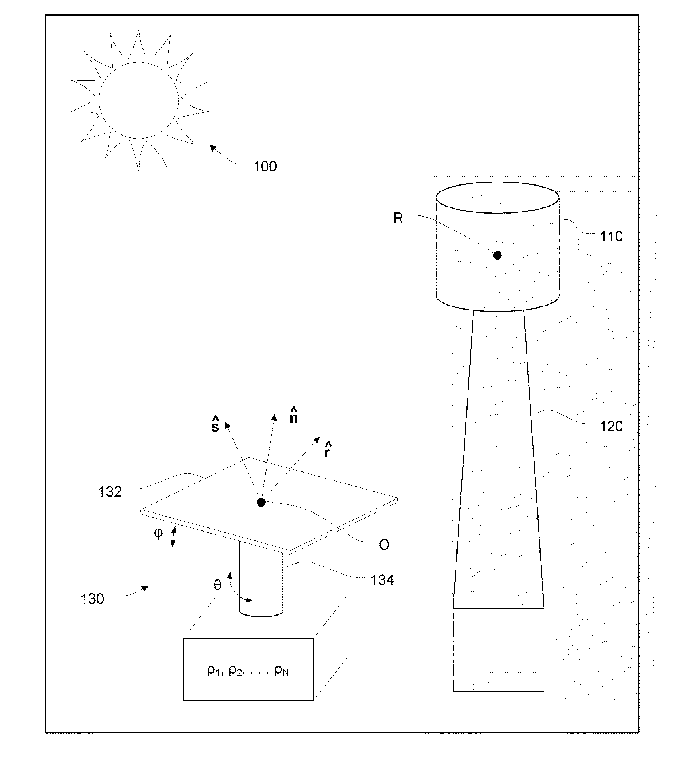
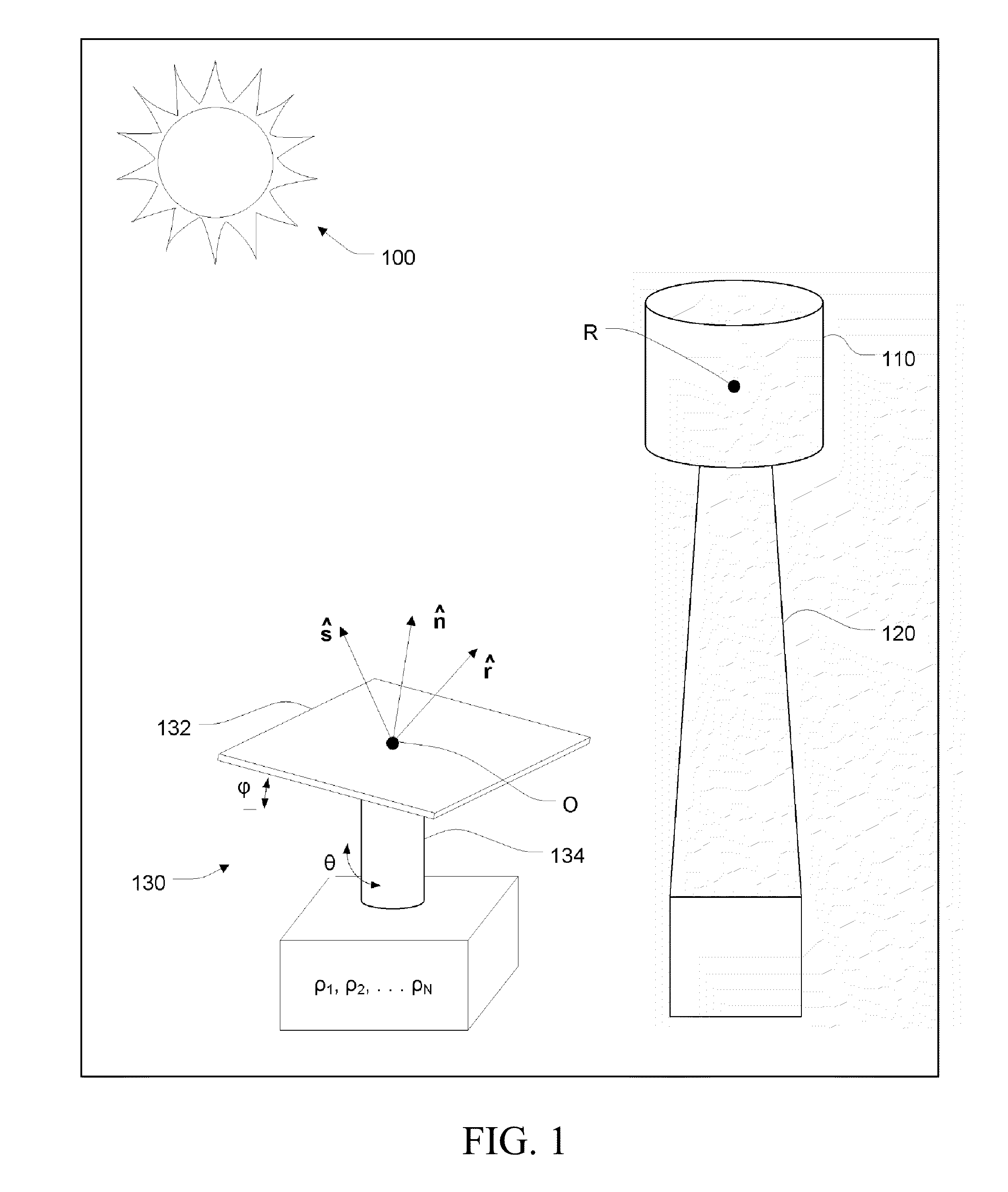
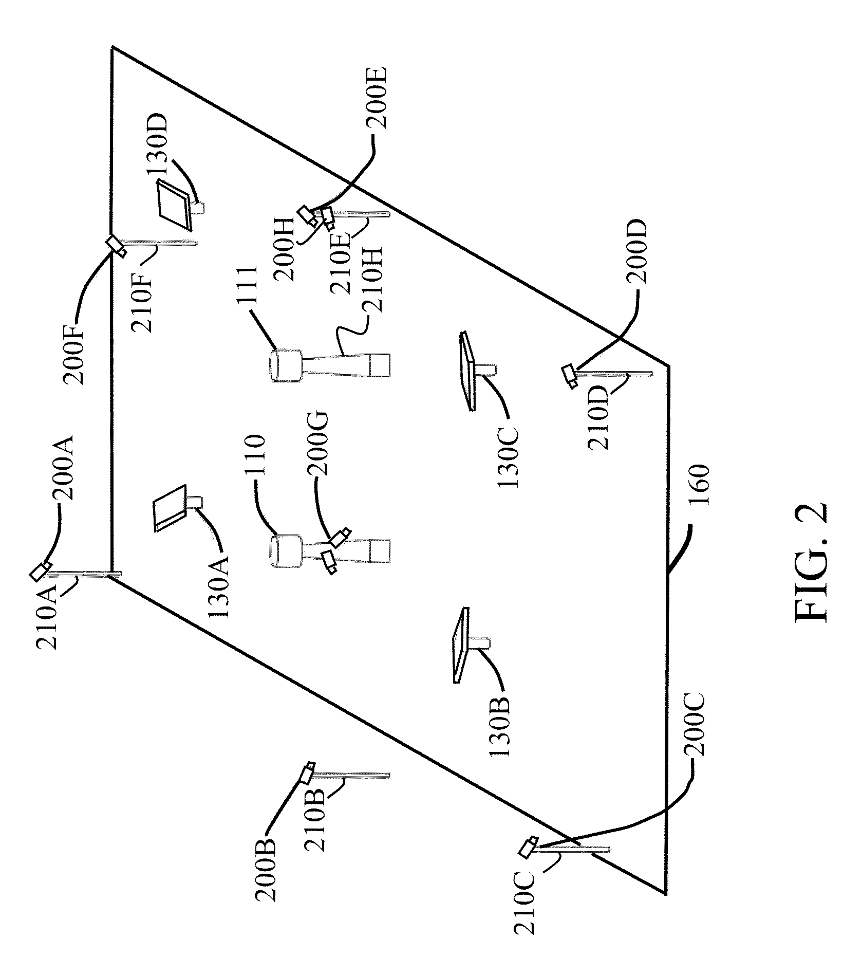
[0041]Rather than ground-mounted cameras and target screens, one or more cameras may be mounted atop poles and directed toward the heliostat field. A heliostat which reflects the sun toward a camera can be imaged, under suitable filtering, as a small compact region of the image sensor—a “blob”; non-contiguous heliostats can be imaged simultaneously at non-adjacent regions of the image sensor, and therefore significant parallelism is possible, and in practice it may be limited by the heat-rejection system protecting the camera and / or the proximity of far-away heliostats as they are imaged onto the image sensor. Accordingly, heliostat tracking parameters may be estimated after each heliostat's mirror is oriented so as to produce reflections into all cameras visible to it, e.g., in round robin fashion, and over several sun positions.

[0042]Heliostat calibration refers to estimating the geometric parameters necessary for a heliostat to reflect the sun continuously into a receiver accordi...


PUM


Abstract

Systems and methods of calibrating heliostat parameters for subsequent open-loop sun-tracking, the calibration based on driving artificial light source reflections from one or more heliostats into one or more image sensors.

Description

[0001]This application is a continuation-in-part of International Application No. PCT / US09 / 53046 filed Aug. 6, 2009, which claims the priority and benefit of U.S. Provisional Patent Application Ser. No. 61 / 137,917, filed Aug. 6, 2008, which are hereby incorporated herein by reference in their entirety for all purposes.TECHNICAL FIELD[0002]The present invention relates generally to heliostat tracking calibration in a solar power plant, and more particularly to heliostat tracking calibration based on artificial light sources.BACKGROUND OF THE INVENTION[0003]Heliostat calibration refers to estimating a set of parameters, e.g., mounting position and angular pose, which are necessary for issuing tracking efficient commands to a heliostat in a central receiver plant. U.S. Pat. No. 4,564,275, issued Jan. 14, 1986 to K. Stone describes a calibration method and system whereby heliostats are commanded to reflect the sun to a calibrating target screen located below the actual receiver aperture...

Claims


Application Information

Patent Timeline
IPC IPC(8): F24J2/38F24S50/20
CPCF24J2/07F24J2/10F24J2/38Y02E10/47G01S3/7803G01S3/7861Y02E10/41F24J2002/385F24S20/20F24S23/70F24S50/20F24S2050/25Y02E10/40
Inventor ZAVODNY, MAXIMILIANREZNIK, DAN S.FORTE, MICHAEL JAMES
Owner SEPCOIII ELECTRIC POWER CONSTR CO LTD
Why Eureka
Try Eureka