Coupling track coding-decoding processing method, audio coding device and decoding device

A processing method and channel technology, applied in the field of audio coding, can solve problems such as large codec redundancy, and achieve the effect of reducing codec redundancy and bit rate

Inactive Publication Date: 2007-11-14
VIMICRO CORP
View PDF0 Cites 5 Cited by
  • Summary
  • Abstract
  • Description
  • Claims
  • Application Information

AI Technical Summary

Problems solved by technology

[0011] When there are multiple channels, the above-mentioned codec device performs the same processing on each channel, so for coupled channels, when there is a strong correlation between the channels, the above-mentioned codec process will exist Large codec redundancy

Method used


Image

  • Coupling track coding-decoding processing method, audio coding device and decoding device
  • Coupling track coding-decoding processing method, audio coding device and decoding device
  • Coupling track coding-decoding processing method, audio coding device and decoding device

Examples


Embodiment Construction
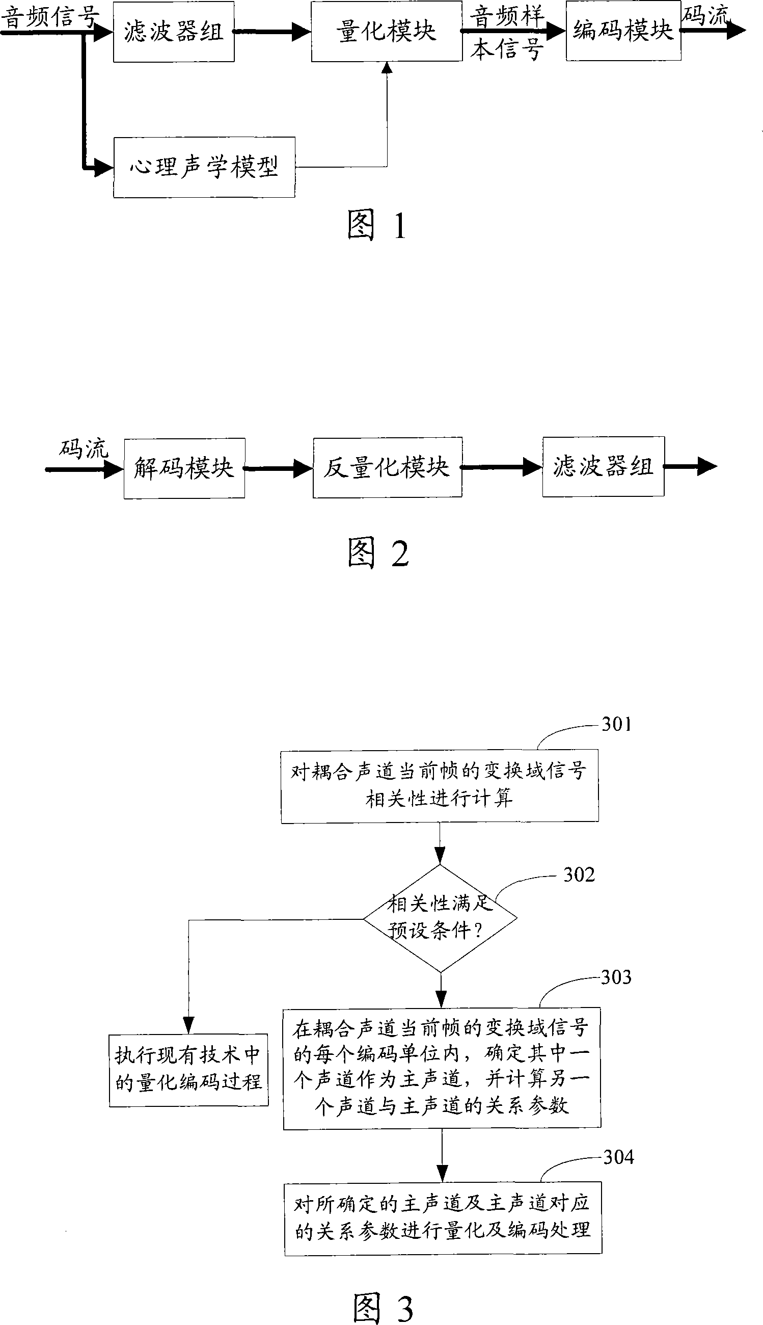
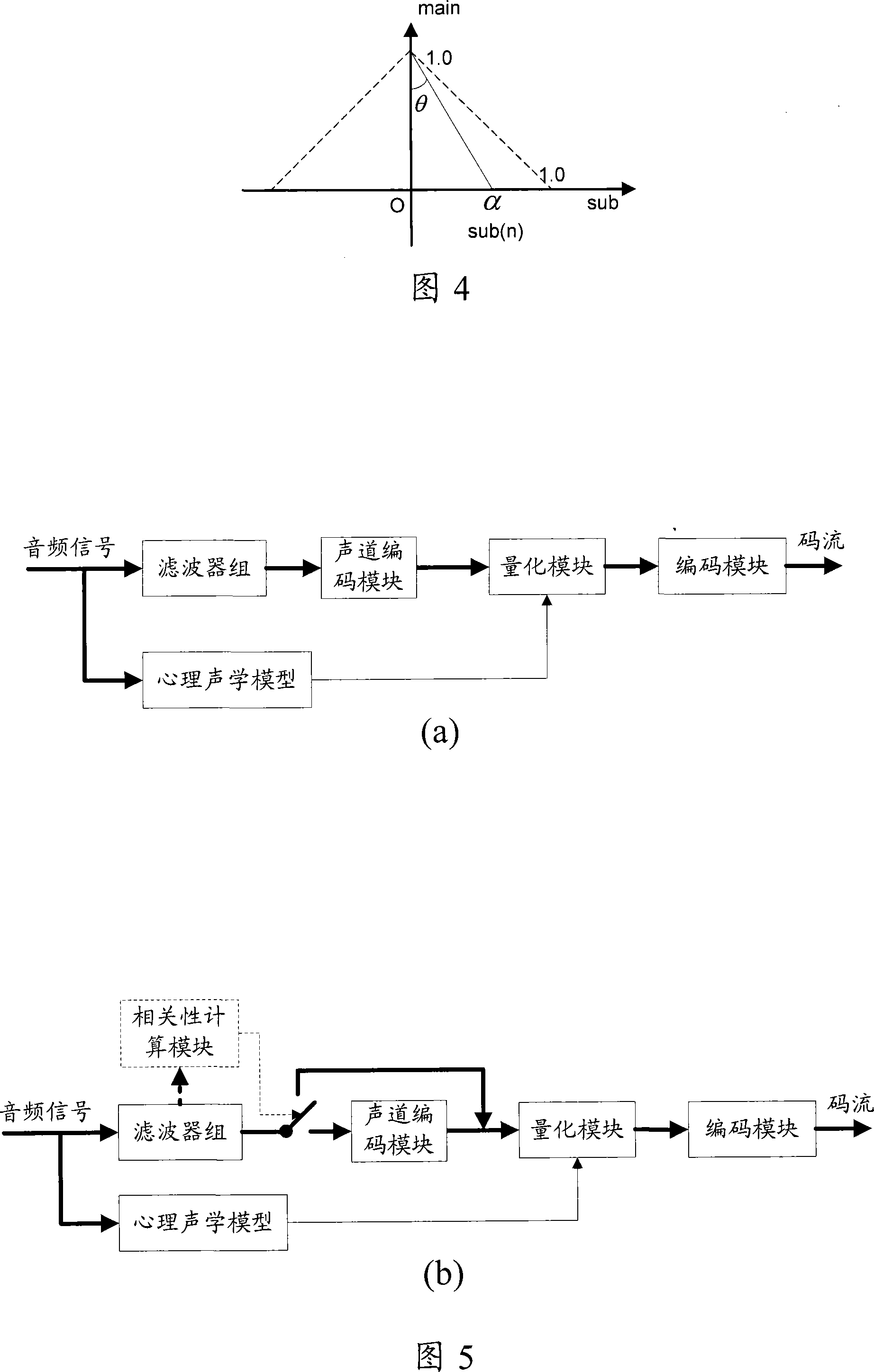
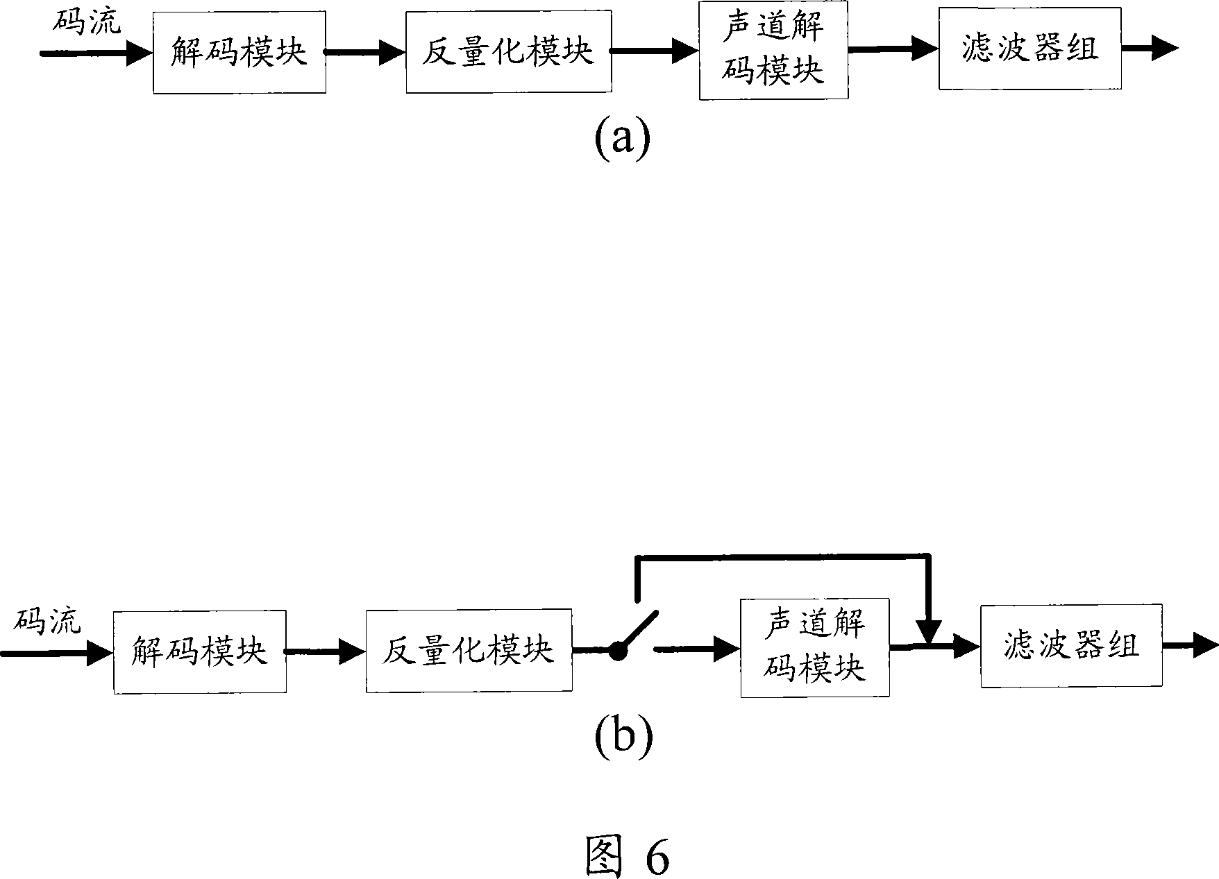
[0037] The basic idea of ​​the present invention is: when coding, in each coding unit of the current frame transform domain signal of the coupling channel, determine one of the channels as the main channel, and calculate the relationship parameter between the other channel and the main channel ; Quantize and encode the main channel and related parameters. During decoding, for the transform domain signal obtained after dequantization, in each coding unit, the coupled channel is restored according to the main channel and the relationship parameters between the other channel and the main channel. Thereby reducing codec redundancy. Wherein, the sound channel mentioned in the present invention refers to the signal corresponding to the sound channel.

[0038] In order to make the object, technical solution and advantages of the present invention clearer, the present invention will be further described in detail below in conjunction with the embodiments and accompanying drawings.

...


PUM


Abstract

The invention discloses a coupled channel coding processing method, comprising: in each code unit of current frame transform domain of the coupled channel, determining a channel as main channel and calculating the relation parameters of another channel and the main channel; making quantization and coding processing on the main channel and the relation parameters. And the invention discloses a coupled channel decoding processing method, comprising: for the transform domain signal derived from inverse quantization and recovering the coupled channel according to the main channel and the relation parameters; besides, the invention discloses an audio coder and decoder. And the invention can effectively reduce coding and decoding redundancy rate and raise coding efficiency.

Description

technical field [0001] The present invention relates to audio coding technology, in particular to a coding processing method, a decoding processing method, an audio coding device and an audio decoding device for coupling sound channels. Background technique [0002] Currently, a structural diagram of an audio encoding device is shown in FIG. 1 , including: a filter bank, a psychoacoustic model, a quantization module, and an encoding module. [0003] Wherein, the filter bank is used for time transform domain mapping, maps the input audio signal from the time domain to the transform domain, and outputs the mapped transform domain signal. Among them, the transform domain or the frequency domain generally refers to the signal representation results obtained by various transform methods for the convenience of signal processing. These transform methods include: Fourier transform (FFT), modified discrete cosine transform (MDCT) and wavelet transform (wavelet transform). )Wait. ...

Claims


Application Information

Patent Timeline
Patent Type & Authority Applications(China)
IPC IPC(8): G10L19/02G10L19/008
Inventor 王箫程
Owner VIMICRO CORP
Why Eureka
Try Eureka