Light-emitting diode packaging method

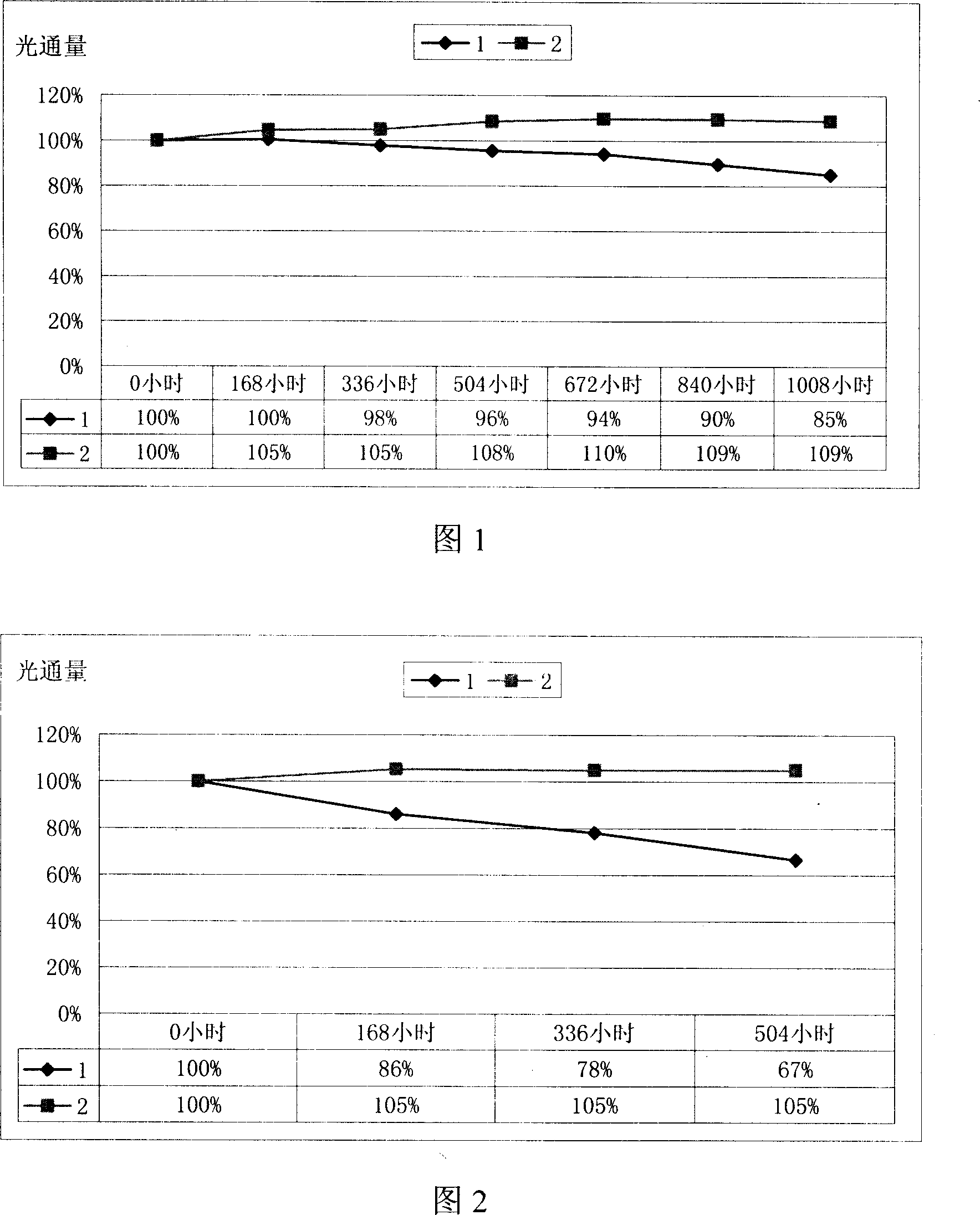
A technology of light-emitting diodes and packaging methods, which is applied to electrical components, circuits, semiconductor devices, etc., can solve the problems of light decay, yellowing of insulating glue, and high temperature, and achieve the effect of reducing light decay rate.

Inactive Publication Date: 2007-11-14
NINGBO ANDY OPTOELECTRONIC CO LTD
View PDF0 Cites 2 Cited by
  • Summary
  • Abstract
  • Description
  • Claims
  • Application Information

AI Technical Summary

Problems solved by technology

The theoretical lifespan of light-emitting diodes is about 100,000 hours. However, when the light-emitting diodes emit light after receiving positive and negative voltages at both ends, they will generate a certain amount of heat. If the heat is not conducted out quickly, it will heat up around the chip. On the one hand, the temperature is higher than the junction temperature of the chip, so that the chip itself fails; The light will be absorbed by the yellowed insulating glue (silver glue) or

Method used


Image

  • Light-emitting diode packaging method

Examples


Example Embodiment

[0022] The light-emitting diode packaged according to the packaging method of the present invention includes a bracket and a light-emitting diode die, the light-emitting diode die is fixed on the holder, and a layer of polydimethyl silicone is provided on the light-emitting surface of the light-emitting diode die. Transparent medium.

[0023] The packaging process of the light emitting diode disclosed in this embodiment includes the following steps:

[0024] Step 1: Dispensing glue, that is, dispensing insulating glue into the reflector cup of the bracket.

[0025] Step 2: Bonding, that is, placing the prepared die on the support of the insulating glue.

[0026] Step 3: Baking after solidification, that is, putting the semi-finished product with solid crystal grains into a high-temperature oven for baking, so that the crystal grains are fixed and adhered to the bracket.

[0027] Step 4: Wire bonding, that is, two gold wires are drawn from the baked crystal grains on the positive a...


PUM


Abstract

One light emitter diode seal method, including following step: drip insulation glue into support reflection cup; place prepared crystal grains on to the support; bake the crystai grains to be adhered to the support; lead two dold wires at positive pole and negative pole; blend poly-dimethyl-silicone and curing agent in a proportion and fully mix them; drip the blended material on the lighr emitting surface of LED grains to form a layer light transmission medium; bake the medium to be cured, and so on.

Description

【Technical Field】 [0001] The present invention relates to a method for packaging light emitting diodes, more specifically, to a method for packaging light emitting diodes with low light attenuation and long life. 【Background technique】 [0002] Light-emitting diode is a kind of semiconductor light-emitting device, which is widely used as indicator light, display screen and so on. Light-emitting diodes are known as the fourth-generation lighting source to replace fluorescent lamps and incandescent lamps. The theoretical life of the light-emitting diode is about 100,000 hours. However, when the light-emitting diode emits light after passing the positive and negative voltages at both ends, it generates a certain amount of heat. If the heat is not quickly transferred out, it will heat up around the chip. On the one hand, the temperature is higher than the junction temperature of the chip, causing the chip itself to fail; on the other hand, it causes the surrounding packaging material...

Claims


Application Information

Patent Timeline
IPC IPC(8): H01L33/00H01L33/48H01L33/56
Inventor 占贤武
Owner NINGBO ANDY OPTOELECTRONIC CO LTD
Why Eureka
Try Eureka