Supercharge Your Innovation With Domain-Expert AI Agents!

Radio transmission method, radio reception method, radio transmission apparatus and radio reception apparatus

A technology of radio transmission and reception methods, applied in the field of radio transmission, can solve the problems of degraded reception performance, incorrect channel compensation of data signals, degraded reception performance, etc., and achieve the effects of improving reception performance, suppressing PAPR, and realizing waveform shaping

Inactive Publication Date: 2007-11-14
FUJITSU LTD
View PDF1 Cites 21 Cited by
  • Summary
  • Abstract
  • Description
  • Claims
  • Application Information

AI Technical Summary

Problems solved by technology

[0067] As shown in Fig. 19, in the case where the roll-off ratios α of the waveform shaping filters 117-i and 119 adopted for the data signal and the pilot signal are the same but the bandwidths are different, for example, a low-quality pilot signal may be mapped on the data signal Near both ends of the occupied frequency band of , and since the channel distortion is different between the two signals, the reception performance deteriorates in the receiving station 200
[0068] That is, for example, at the right end (higher frequency side) of the occupied frequency band of the data signal, a low-quality (S / N) pilot signal whose amplitude is attenuated by the waveform shaping filter 119 is mapped for a part of the effective subcarrier, which reduces channel estimation accuracy and degrade reception performance
On the other hand, at the left end (lower frequency side) of the occupied frequency band of the data signal, for part of the subcarriers, channel distortion occurs between the data signal and the pilot signal due to devices including the waveform shaping filters 117-i and 119. different between, which will cause incorrect channel compensation for the data signal and degrade the reception performance of the data signal

Method used


Image

  • Radio transmission method, radio reception method, radio transmission apparatus and radio reception apparatus
  • Radio transmission method, radio reception method, radio transmission apparatus and radio reception apparatus
  • Radio transmission method, radio reception method, radio transmission apparatus and radio reception apparatus

Examples


Embodiment Construction

[0104] [A] Description of Examples

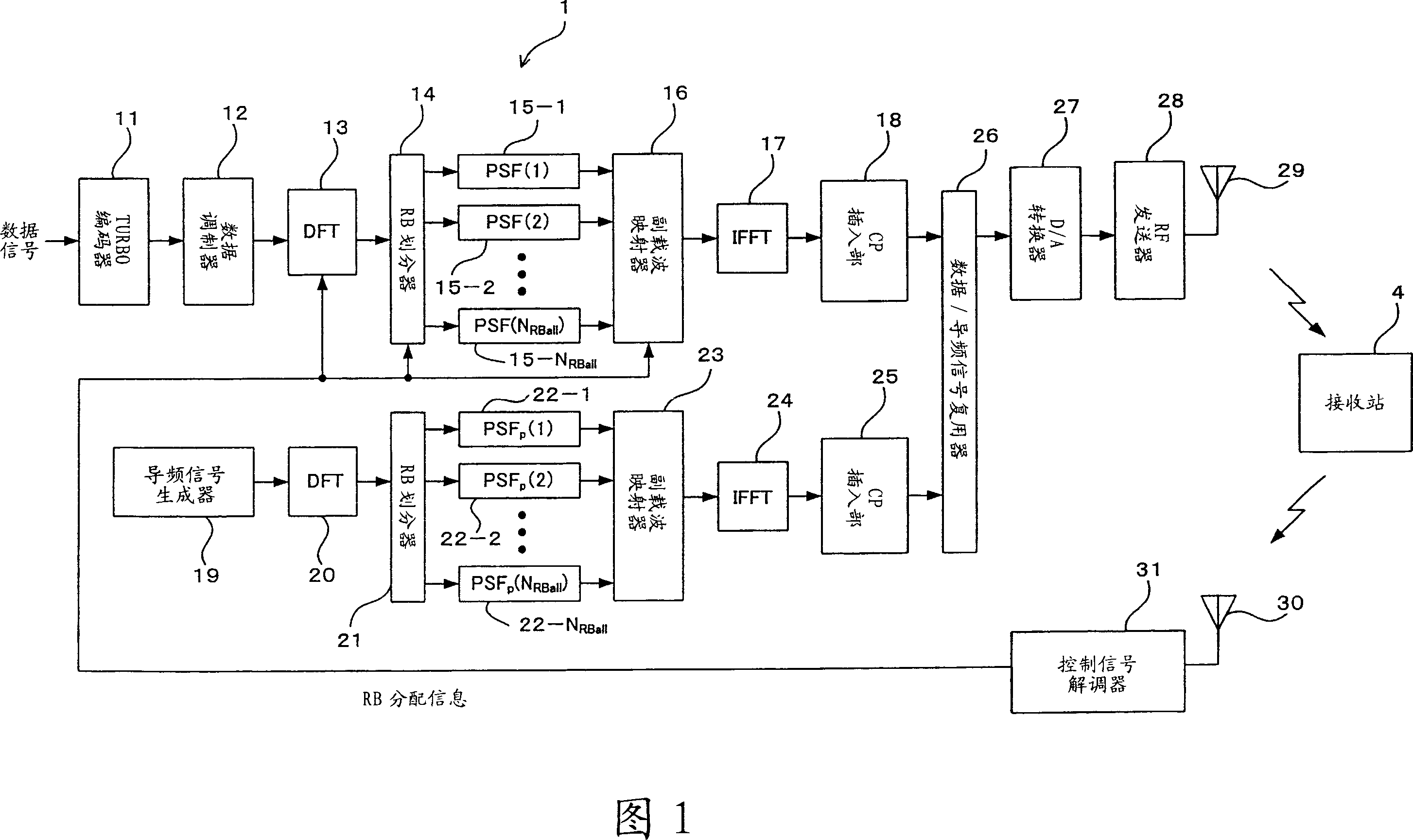
[0105] 1 and 4 are functional block diagrams showing the configuration of a system employing DFT-extended OFDM as a single carrier transmission mode as a radio communication system according to an embodiment of the present invention, and FIG. 1 is about a transmission station (radio transmission device) 1, and FIG. 4 is a functional block diagram regarding the configuration of a receiving station (radio receiving apparatus) 4. As described above with reference to FIG. 10(A), FIG. 10(B) and FIG. 12, this embodiment is also based on the FDMA communication mode, in which the system frequency band is divided into fixed frequency bands (RB), and the frequency bands with arbitrarily set numbers are used as units to transmit data signals, while pilot signals are transmitted in a dispersed arrangement throughout the system band. Incidentally, in FIGS. 1 and 4 , point-to-point communication is performed between the sending station 1 and the receivi...


PUM


Abstract

A pilot signal is transmitted with a predetermined frequency band (N e X N Rball X (1 + +-)) and a data signal is transmitted with a partial band (RB) of the frequency band, and the pilot signal and the data signal to be transmitted with at least the partial band (RB), are controlled its waveform to have the same waveforms in the frequency domain. Thus, in the case of controlling waveforms of the pilot signal and the data signal which have different occupied bands, it is possible to, in a portion of the occupied band for the data signal, avoid the mapping of a low-quality pilot signal or the like, enhance the data signal demodulation capability and improve the data signal reception characteristic while suppressing PAPR.

Description

technical field [0001] The present invention relates to a radio transmission method, a radio reception method, a radio transmission device, and a radio reception device. For example, the present invention relates to a technology suitable for a next-generation mobile communication system using DFT as a radio access method (Discrete Fourier Transform) - Extended OFDM (Orthogonal Frequency Division Multiplexing) method. Background technique [0002] Frequency Utilization is high and the PAPR (Peak-to-Average Power Ratio) of the transmitted signal is low. In order to meet these requirements, it has been discussed to utilize FDMA (Frequency Division Multiple Access) with respect to Single Carrier (SC) (for example, see Non-Patent Document 1 mentioned later). As one of the radio access schemes that can satisfy the above requirements, special attention has been paid to the DFT-extended OFDM mode (for example, see Non-Patent Documents 2 and 3 mentioned later). [0003] One featur...

Claims


Application Information

Patent Timeline
Patent Type & Authority Applications(China)
IPC IPC(8): H04B7/26H04B7/005H04B7/204H04L5/12H04J1/00H04J11/00H04L27/01
CPCH04L27/2636H04L25/03834H04L27/2647H04L27/2613H04L27/26132H04L5/0048H04L27/261H04L27/2614
Inventor 实川大介关宏之
Owner FUJITSU LTD
Features
  • R&D
  • Intellectual Property
  • Life Sciences
  • Materials
  • Tech Scout
  • Unparalleled Data Quality
  • Higher Quality Content
  • 60% Fewer Hallucinations
Learn More