Pixelated detectors with depth of interaction sensitivity

A technology of interaction depth and photodetector, which is applied in the field of medical imaging, can solve problems such as noise sensitivity, and achieve the effect of improving resolution and improving image resolution

Inactive Publication Date: 2007-11-14
KONINKLIJKE PHILIPS ELECTRONICS NV
View PDF1 Cites 24 Cited by
  • Summary
  • Abstract
  • Description
  • Claims
  • Application Information

AI Technical Summary

Problems solved by technology

However, since the position of each photodetector

Method used


Image

  • Pixelated detectors with depth of interaction sensitivity
  • Pixelated detectors with depth of interaction sensitivity
  • Pixelated detectors with depth of interaction sensitivity

Examples


Embodiment Construction

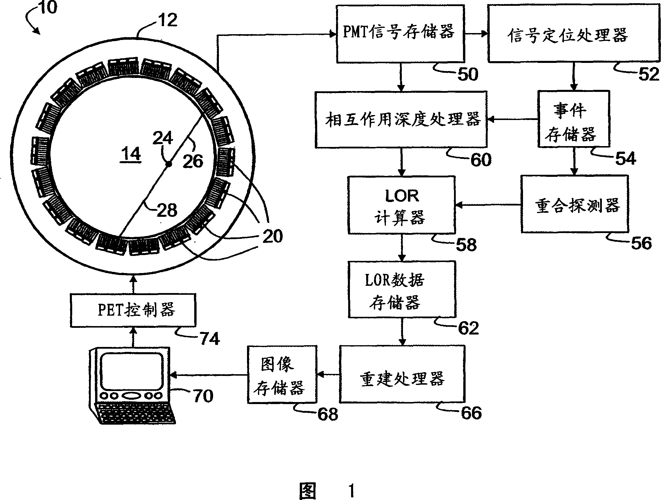
[0020] A positron emission tomography (PET) system includes a PET scanner 10 having a stationary annular gantry 12 surrounding an imaging region 14 . Mounted around the ring-shaped gantry are a plurality of pixelated radiation detector modules 20 with their radiation-sensitive sides facing the imaging region 14 .

[0021] A human imaging subject or other types of imaging subjects are placed in the imaging area 14 . The radiopharmaceutical administered to the imaged subject produces a nuclear decay event that emits a positron as one of the products. The positron rapidly annihilates with a nearby electron, producing a pair of opposing 511keV gamma rays. As an example, an example of a nuclear decay event 24 is illustrated in FIG. 1 , the trajectories of two opposing gamma rays extending from the nuclear decay event 24 in opposite directions, indicated by lines 26 , 28 . Each gamma ray strikes a pixelated radiation detector module 20 .

[0022] With continued reference to FIG. ...


PUM


Abstract

A radiation detector (20, 20') includes scintillator pixels (30) that each have a radiation-receiving end, a light-output end, and reflective sides extending therebetween. The reflective sides have a reflection characteristic (40, 40', 42, 44) varying between the radiation-receiving end and the light-output end such that a lateral spread of light emanating from the light-output ends of the scintillator pixels responsive to a scintillation event generated in one of the scintillator pixels depends upon a depth of the scintillation event in the scintillator pixel. A plurality of light detectors (46) optically communicate with the light-output ends of the scintillator pixels to receive light produced by scintillation events.

Description

technical field [0001] The following relates to the field of medical imaging. It finds particular application in positron emission tomography (PET) scanners and systems and will therefore be described with particular reference to this field. More generally, application to medical imaging scanners and systems using scintillation-based radiation detectors, such as computed tomography (CT) scanners and systems, nuclear imaging cameras and systems, gamma cameras, and the like. Background technique [0002] In positron emission tomography, a human or other imaging subject is administered a radiopharmaceutical. The radioactive decay event that occurs in radiopharmaceuticals emits a positron, which in turn produces two gamma rays with energy 511 keV in opposite directions in a positron-electron annihilation event. Radiation detectors surrounding the imaged object detect these two opposing gamma rays, and the detection points define lines of response between each other. Response ...

Claims


Application Information

Patent Timeline
IPC IPC(8): G01T1/202
CPCA61B6/037G01T1/202G01T1/1644G01T1/2002
Inventor T·L·劳伦斯S·E·库克
Owner KONINKLIJKE PHILIPS ELECTRONICS NV
Why Eureka
Try Eureka