
Method for forming a movable matrix image and device for a light-emitting diode running letters

A technology of light-emitting diodes and diodes, applied in the direction of identification devices, instruments, etc., can solve the problems such as the structure is not optimized, hindered, and does not allow to increase the quality of the image field of view of the displayed information resolution, so as to enhance reliability and control, and reduce costs. Effect

Inactive Publication Date: 2007-11-14
迪斯加有限公司
View PDF0 Cites 0 Cited by
  • Summary
  • Abstract
  • Description
  • Claims
  • Application Information

AI Technical Summary

Problems solved by technology

[0010] One of the reasons preventing the attainment of the desired technical achievement when the known device is applied as a prototype to an alphanumeric and graphic information display is that the information strip of the device contains colored display units, produced in the form of three-color light-emitting diodes , by sequentially arranging along the column of the displayed image, forming the column of the field of view image, structurally not optimized, the device does not allow to increase the resolution of the displayed information and the quality of the field of view of the image displayed in the display device, respectively

Method used


Image

  • Method for forming a movable matrix image and device for a light-emitting diode running letters
  • Method for forming a movable matrix image and device for a light-emitting diode running letters
  • Method for forming a movable matrix image and device for a light-emitting diode running letters

Examples


Embodiment Construction

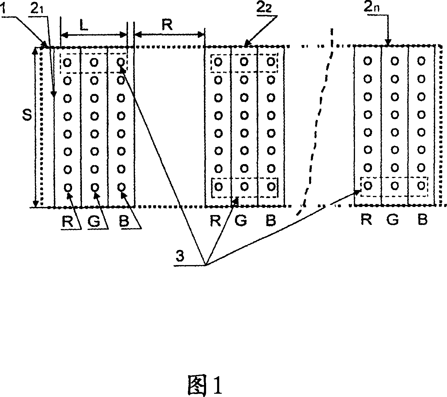
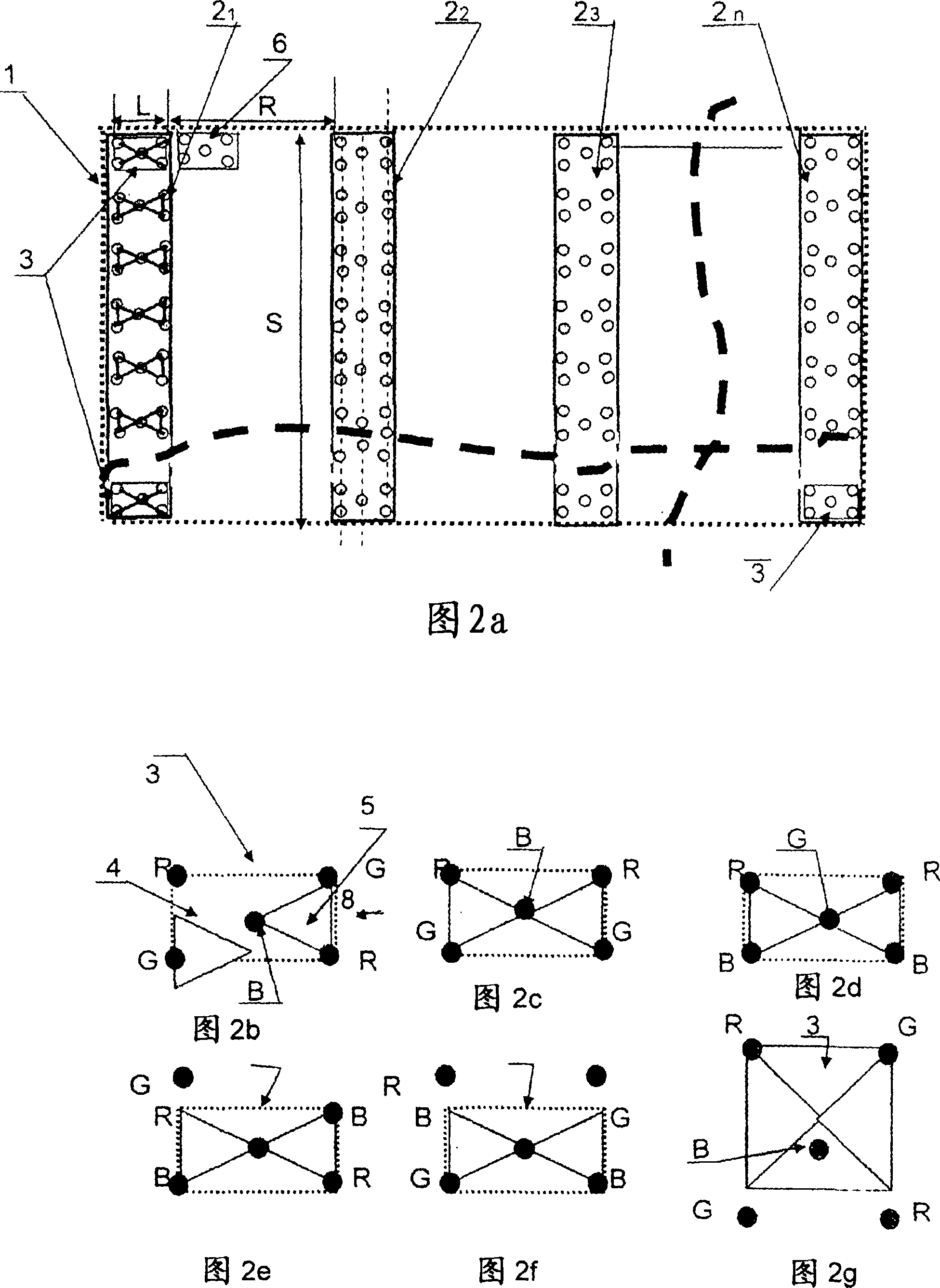
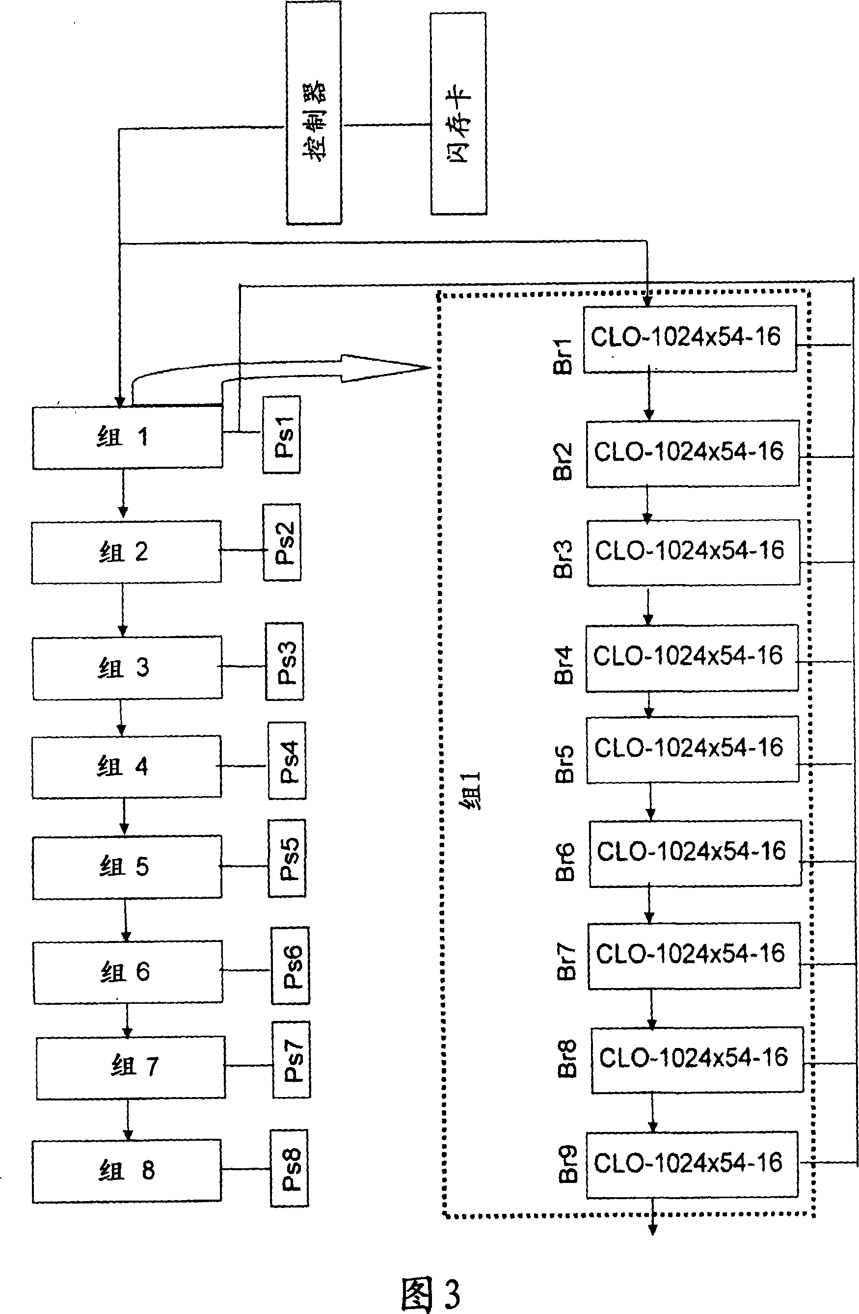
[0029] The working principle of the LED scrolling characters displaying alphanumeric and graphic information is based on the movable matrix image formed by the "residual image" effect. Specific quality provisions on an image are instantly displayed. The human eye follows the image, applying the current image to a previous image, and as a result, the illusion of a combined image appears, although in reality it contains a certain number of fragments. Fragments contain lines and row units, both of which are formed from lines of information. In Fig. 2a, the imaginary unit of the line 6 between the row information strips of the image 2 is drawn. Implement the device provided in the product "Light Emitting Diode Scrolling Characters", "INCOTEX-Display System" LOR CLO-1204×54-16-00 for displaying color alphanumeric and graphic information, and in each information bar (Figure 2 ) in the block diagram (Fig. 3), the length of light cluster 3 is equal to 16mm, and 54mm is the informati...


PUM


Abstract

The enclosure assembly comprises a stationary member including at least two substantially parallel sidewalls, the sidewalls, the sidewalls partially defining a cavity in which the fingerprint sensor is disposed. An access piece, configured to move relative to the stationary member, has a surface area larger than the surface area of the fingerprint sensor and further includes a conductive portion electrically coupled to ground. A movement apparatus is preferably mechanically coupled to the stationary member and the moveable access piece. The movement apparatus is configured to maintain the moveable access piece in a position covering the fingerprint sensor and yet to allow motion of the moveable access piece relative to the stationary member so as to expose the fingerprint sensor. According to another embodiment, a method for enrolling a composite image of an object using a fingerprint sensor is provided. According to an embodiment, the method comprises the steps of receiving a finger disposed over a fingerprint sensor in a first stationary position; capturing a first image of a first portion of the finger with the fingerprint sensor; causing the finger to be repositioned over the fingerprint sensor in a second stationary position; capturing a second image of a second portion of the finger with the fingerprint sensor; and constructing a representative image of the finger from the first and second images.

Description

technical field [0001] This group of inventions relates to display technology, and can be used when designing display devices for public information on indoor and outdoor objects. The display devices display color alphanumerics, graphic information, and symbols with certain color codes in the form of light-emitting diode scrolling characters. dynamic image. Background technique [0002] Display devices for forming dot-matrix images and information are well-known methods in which the "residual image" effect that occurs in the human eye when displays made based on light-emitting diodes are moved rapidly has been exploited (1). [0003] One of the reasons preventing the attainment of the desired technical result when the known method is applied to form matrix images and devices is that the method does not allow the generation of display devices such as information lines for scrolling. [0004] There are well known methods for forming movable matrix images and display devices p...

Claims


Application Information

Patent Timeline
IPC IPC(8): G09F9/302G09F9/33
Inventor 尤里·B·索科洛夫罗伯特·P·巴拉诺维奇瓦伊塔利·A·斯威瑞朵夫米查利·V·斯特乐尼科夫
Owner 迪斯加有限公司
Learn More