Carbon nano-pipe array/laminated composite and its production
A carbon nanotube array, layered material technology, applied in metal material coating process, coating, layered products and other directions, can solve the problems of carbon nanotube arrays that have not been reported, and achieves easy engineering scale-up and mass production. Effect
- Summary
- Abstract
- Description
- Claims
- Application Information
AI Technical Summary
Benefits of technology
Problems solved by technology
Method used
Image
Examples
preparation example Construction
[0024] The steps of the preparation method of the above-mentioned carbon nanotube array / layered material composite are: 1) making the precursor of the catalyst active component into a homogeneous solution, immersing the layered material carrier in the homogeneous solution, and drying it at 100~ Calcined at 500°C to form a catalyst with a structure in which the metal active components are distributed between the layered material carrier sheets; the active components of the catalyst are Fe, Co, Ni, Mo, W, Cu or rare earth elements, Wherein the active component accounts for 0.1% to 50% of the mass of the catalyst; the catalyst active component precursor is the nitrate, chloride or metallocene compound corresponding to the metal;
[0025] 2) The catalyst is placed in a reactor, and a carbon nanotube / layer material composite is prepared through a chemical vapor deposition process.
[0026] In the present invention, the chemical vapor deposition process uses methane, ethane, ethylen...
Embodiment 1
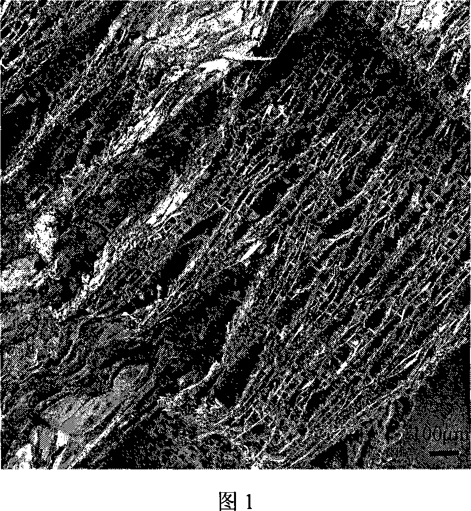
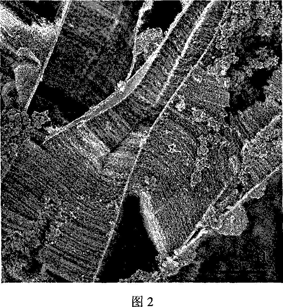
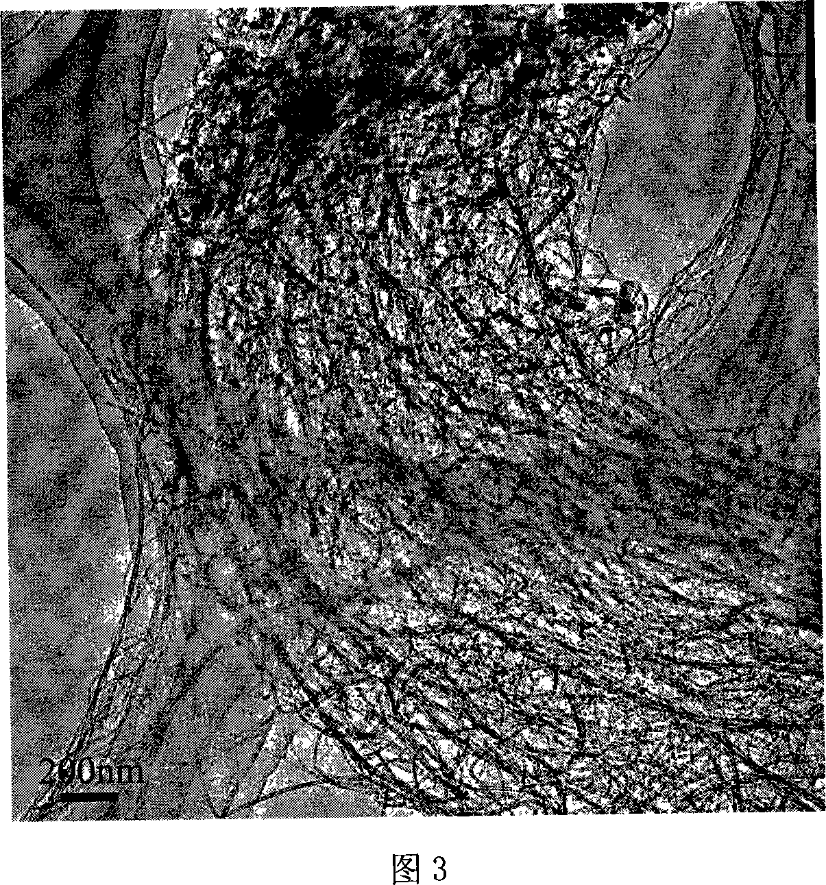
[0028] Example 1: A carbon nanotube array / layered material composite was prepared by using mica as a catalyst carrier through a fixed bed.
[0029] Mica is a natural layered material. Take 40.4g Fe(NO 3 ) 3 9H 2O was dissolved in 400ml of deionized water, and then 200g of mica was impregnated into the above solution. After being fully impregnated, the solution basically penetrates into the mica. The impregnated mica was then dried at 110 °C for 12 hr. Then it was calcined at 500° C. for 30 minutes and then cooled to form a catalyst with a structure in which the metal active component is distributed between the support sheets of the layered material, and the active component iron accounts for 2.8% of the mass fraction of the catalyst. Then take 1 g and place it in a fixed-bed reactor with a diameter of 30 mm and a length of 1200 mm, using argon and hydrogen as carrier gases with flow rates of 600 sccm and 20 sccm respectively. Under this atmosphere, the reaction temperatu...
Embodiment 2
[0031] Example 2: Using vermiculite as a catalyst carrier to prepare a carbon nanotube array / layered material composite through a fixed bed.
[0032] Vermiculite is a naturally layered material. Take 808g Fe(NO 3 ) 3 9H 2 O was dissolved in 400ml of methanol, and then 2kg of vermiculite was impregnated into the above solution. After being fully impregnated, the solution basically permeates between the vermiculites. Then the impregnated vermiculite was dried at 100° C. for 12 hours. Calcined at 450°C for 60 minutes and then cooled to a catalyst with a structure in which the metal active component is distributed between the support sheets of the layered material. The active component iron accounts for 5.6% of the mass fraction of the catalyst, and its appearance is shown in Figure 5. . A fixed bed with a diameter of 200mm and a length of 1000mm will be placed, and argon and hydrogen will be used as carrier gases with flow rates of 20000 sccm and 200 sccm respectively. Und...
PUM
 Abstract
Description
Claims
Application Information
 - R&D
- Intellectual Property
- Life Sciences
- Materials
- Tech Scout
- Unparalleled Data Quality
- Higher Quality Content
- 60% Fewer Hallucinations
Browse by: Latest US Patents, China's latest patents, Technical Efficacy Thesaurus, Application Domain, Technology Topic, Popular Technical Reports.
© 2025 PatSnap. All rights reserved.Legal|Privacy policy|Modern Slavery Act Transparency Statement|Sitemap|About US| Contact US: help@patsnap.com


